ADI-524
The ADI-524 is 4 channel 4-20mA analog to RS485 converter using standard Modbus-RTU protocol. It has dedicated RS485 port for output which need power supply to lit up device or It can work over single USB port having power supply and RS485 output in it.
Please read carefully before starting. Also read the product safety information.
General information
| Download technical specification | Technical Specification |
ADI-524 has 4 opto-isolated analog inputs and RS485/USB output. It is also featured with isolated 24V power output to feed 4-20mA sensors/devices. For baud rate and Modbus address configuration to be done using DIP switch.
Additional USB port make this device perfect to use with industrial computers and gateways having dedicated USB port, as this product is designed according to industry-standards.
It can be mounted on standard DIN rail by using clamps.
Hardware informations
This interface converted is made of single PCB, which is fitted in aluminum housing. The housing is made of a thick, strong aluminum profile with two end plates also made from aluminum. The surface of the housing is finished by anodizing.
At the bottom of the housing there are slots through which DIN rail clamp or any other clamp can be mounted by t-nuts.
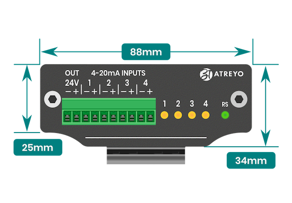
Front view dimensions
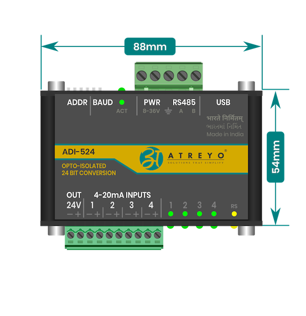
Side view dimensions
Interfaces
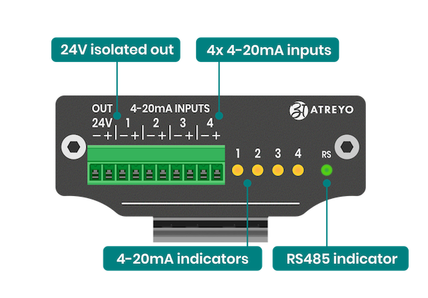
Top view connector and indicators
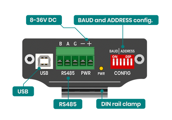
Bottom view connector
Configuration Manual
Please read carefully before starting. Also read the product safety information.
Wiring and connection
The ADI-524 can be powered from a DC power supply in the range of 8-36V. Also, it can be powered from the USB port of a computer or IoT gateway. Both power sources can be connected simultaneously without fear of damage.
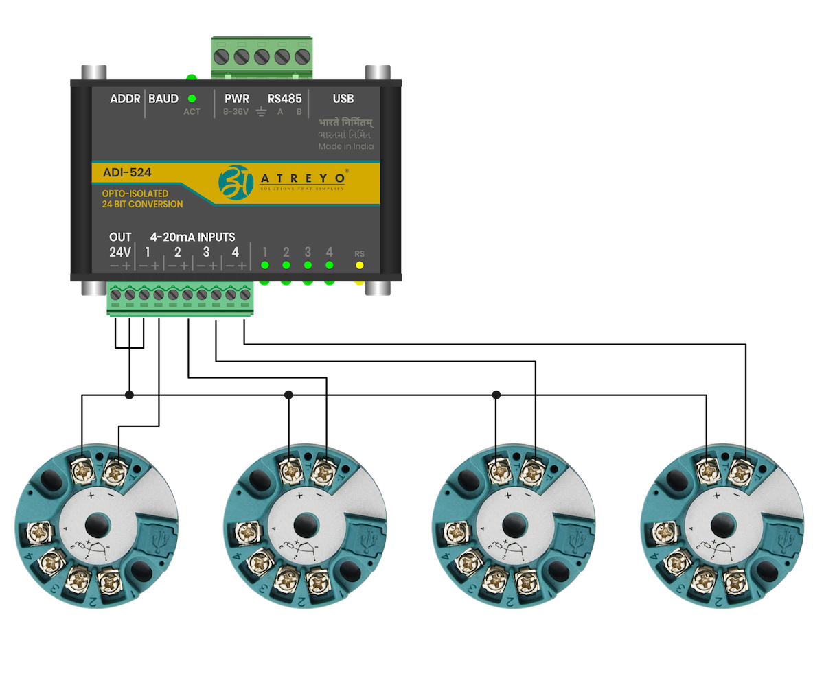
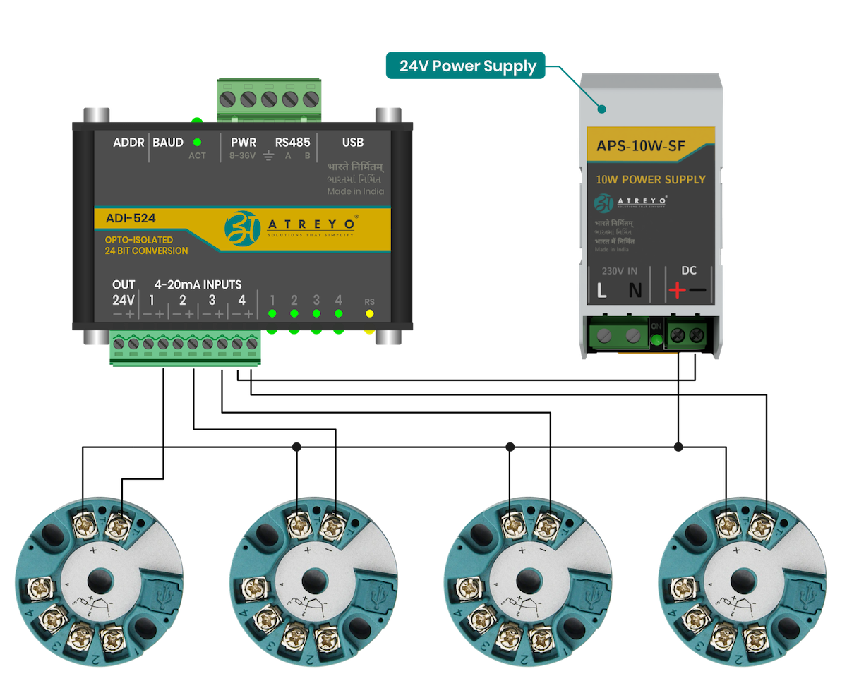
In order to connect sensors with a 4-20mA output, it is necessary to provide them power in the loop. Here are some possible connection methods. Either the built-in isolated 24V power supply can be used or an external current loop power supply can be used.
All current inputs marked as - on the housing are connected together. The isolated 24V, on the other hand, has no galvanic connection to any of the inputs.
Connection Diagrams
Built-in 24V
Connection of four RTD converters using the built-in 24V power supply.
External 24 V
Connection of four RTD converters using the external 24V power supply.
Modbus configuration
It is necessary to set the serial port parameters and the Modbus address using the DIP switch before powering on the device. (reference table for both are given below)
Make sure to reboot/restart device irrespective of any change in DIP switch to be reflected in hardware
MODBUS Serial Port Parameter
| Parameter | Option/range |
| Baudrate | 9600 – 115200 configurable |
| ata bit | 8 |
| Parity | None |
| Stop bit | 1 |
MODBUS Baudrate Configuration
User can set the baud rate using 2 Bit DIP switch. This allows to set baud rate between 9600bps to 115200bps as shown below table.
| Baudrate |
SW1 |
SW2 |
| 9600 | OFF |
OFF |
| 19200 | ON |
OFF |
| 38400 | OFF | ON |
| 115200 | ON | ON |
After setting up the switch, it is necessary to restart the ADI by disconnecting the power supply and, if using USB power, to disconnect it.
MODBUS Address configuration
User can set the slave ID address using 4 Bit DIP switch. This allow 0 to 15 different IDs to be set. The number below the switches are added together and the result will be identifier of the device slave ID.
| Slave ID | SW3 | SW4 | SW5 | SW6 |
| 1 |
OFF |
OFF | OFF | OFF |
| 1 |
ON |
OFF | OFF | OFF |
| 2 |
OFF | ON | OFF |
OFF |
| 3 |
ON |
ON |
OFF | OFF |
| 4 |
OFF |
OFF | ON |
OFF |
| 5 |
ON |
OFF | ON |
OFF |
| 6 |
OFF | ON |
ON |
OFF |
| 7 |
ON |
ON |
ON |
OFF |
| 8 |
OFF | OFF | OFF | ON |
| 9 |
ON |
OFF | OFF | ON |
| 10 |
OFF | ON |
OFF | ON |
| 11 |
ON |
ON |
OFF | ON |
| 12 |
OFF | OFF | ON |
ON |
| 13 |
ON |
OFF | ON |
ON |
| 14 |
OFF | ON |
ON |
ON |
| 15 |
ON |
ON |
ON |
ON |
Protocol Description
Overview
The MODBUS protocol is a widely used communication standard in industrial automation, facilitating master-slave data exchange. It is known for its simplicity and flexibility, making it suitable for a range of applications in connecting intelligent devices.
In MODBUS communication, messages sent from the master to a slave device contain key components: the slave's address, a command (such as "read register" or "write register"), the associated data, and an error-checking field (using LRC or CRC for checksum). As a messaging protocol, MODBUS is independent of the underlying physical layer, meaning it can be implemented over various mediums like RS485 or USB-to-serial interfaces.
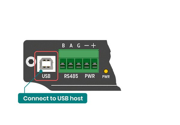
USB interface
ADI-524 has a built-in USB to serial converter, you can plug USB cable and start device configuration as there is no need to install any additional drivers on most operating systems. However, if you find that you need to install drivers, you can download driver - .V1.00 driver.zip
The ADI-524 allows operation via only one interface at a time. Either RS485 or USB. DIP switch settings are necessary when using both interfaces
MODBUS RTU Framing
The ADI-524 module supports standard RTU Modbus protocol for getting the input status and setting/getting the relays status. RTU Modbus Protocol frame is illustrated below:
| Start | Address | Function | Data |
RC Check | End |
| ≥ 3.5 Char | 4 Bits |
8 Bits |
N*8 Bits | 16 Bits | ≥ 3.5 Char |
- Start Address: This identifies the specific device or slave on the network. Each device has a unique address to differentiate it from others.
- Function Code: Specifies the type of operation being requested. Common function codes include:
- 0x04: Read Input Register
- 0x06: Write Single Register
- 0x10: Write Multiple Registers - Starting Address: The address of the first register from which data will be read or to which data will be written
- Number of Registers: Indicates how many registers should be read or written, starting from the specified address.
- CRC (Cyclic Redundancy Check): This is a checksum used to verify the integrity of the data. It is calculated based on the previous fields and helps detect errors in the transmitted data.
Each part of the request plays an important role in ensuring the correctness of Modbus communication. The start address and function code define the operation, and the CRC checksum protects the accuracy of the message.
MODBUS Command examples
04 function code for reading value from input.
Modbus dear query message
| Command: read analog input 1 | ||
| Byte |
Byte description | Example (HEX) |
| 0 |
Slave ID | 01 |
| 1 |
Function code | 04 |
| 2 |
Starting address High | 00 |
| 3 |
Starting address Low | 00 |
| 4 |
Number of Registers High | 00 |
| 5 |
Number of Registers Low | 02 |
| 6 |
CRC AB | 71 |
| 7 |
CRC CD | CB |
| Start |
Slave address |
Function code 04 |
Starting Number |
CRC ABCD 71 CB |
End |
|||
| High | Low | High | Low | |||||
| 00 |
00 |
00 |
02 |
|||||
Modbus response
| Response: Analog Input - 13.40mA | ||
| Byte |
Byte description | Example (HEX) |
| 0 |
Slave ID | 01 |
| 1 |
Function code | 04 |
| 2 |
Byte Count | 04 |
| 3 |
Data 1 | 41 |
| 4 |
Data 2 |
6C |
| 5 |
Data 3 |
CC |
| 6 |
Data 4 |
CD |
| 7 |
CRC AB | BB |
| 8 |
CRC CD | 30 |
The number in 32-bit floating point HEX format 0x416CCCCD in decimal is: 13.40
| Start |
Slave address |
Function code 04 |
Number of bytes | Data | Error check
|
End |
|||
| First register |
Second register |
||||||||
| Data 1 |
Data 2 |
Data 3 |
Data 4 |
||||||
Safety information
Operating environment
- The device is designed to be installed in clean, dust-free and insect-free places
- Operating temperature: -25 ~ 65°C (-13 ~ 149°F).
- Humidity range is 10% to 95% (non-condensing). Use the device in a dry environment.
- Away from heat sources and direct sunlight.
- It must not be exposed to acid fumes, salts and other chemicals.
- The device must not be used in places where there is a risk of gas explosion.
Use in inappropriate conditions may damage the device or shorten its life.
Electrical and power supply safety
- The device is powered with a voltage in the range of 8-36V. Voltage up to 24V is considered safe. Be especially careful when supplying them with higher voltages.
- Use only approved accessories
- Use the supplied power adapter or a good quality certified power adapter with the correct supply voltage range and sufficient power.
- Only use approved accessories like antenna etc.
Only a person with qualification and appropriate knowledge should install the device.
Malfunctioning and damaged device
- Do not disassemble the device.
- Only qualified personnel must service or repair the device or its accessories.
- If water or other liquid has got into the device, or if it looks mechanically damaged, do not connect the device, but take it to an authorized service center.
What to do and what not to do
- You are solely responsible for the use of the device and any consequences of its use.
- Do not store or use the device in harsh environments such as dust, gases, oils, chemical vapors and damp places.
- Do not throw the device and its accessories. Handle with care.
- The device heats up during operation. Ensure proper ventilation.
- If you need to dispose of your device, check your local regulations for recycling and disposal of electronics.
- Route power, Ethernet, and antenna cables properly so that they cannot be accidentally pulled out.
- The device should be used and kept away from small children.