Note that RX of gateway should be connected to TX of USB-UART converter. And TX of gateway to RX of USB-UART converter
--- #### Inserting SIM card Please refer drawing for proper SIM placement. 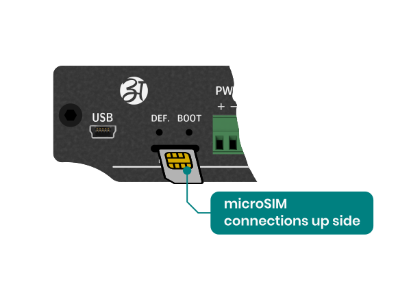 --- ### Connecting configuration application 1. Connect one end of the TTL converter to the window computer. 2. Open AG IoT Configuration application on window PC. 3. Select AG-201, Select COM port and configure port with 9600,N,1,8 and click open port After port connection, click connect. 4. Once the connection is established successfully, enter the password "atreyo" to access the configuration mode. This is the default password. 5. Click CONFIGON and configure device parameter, as shown below: [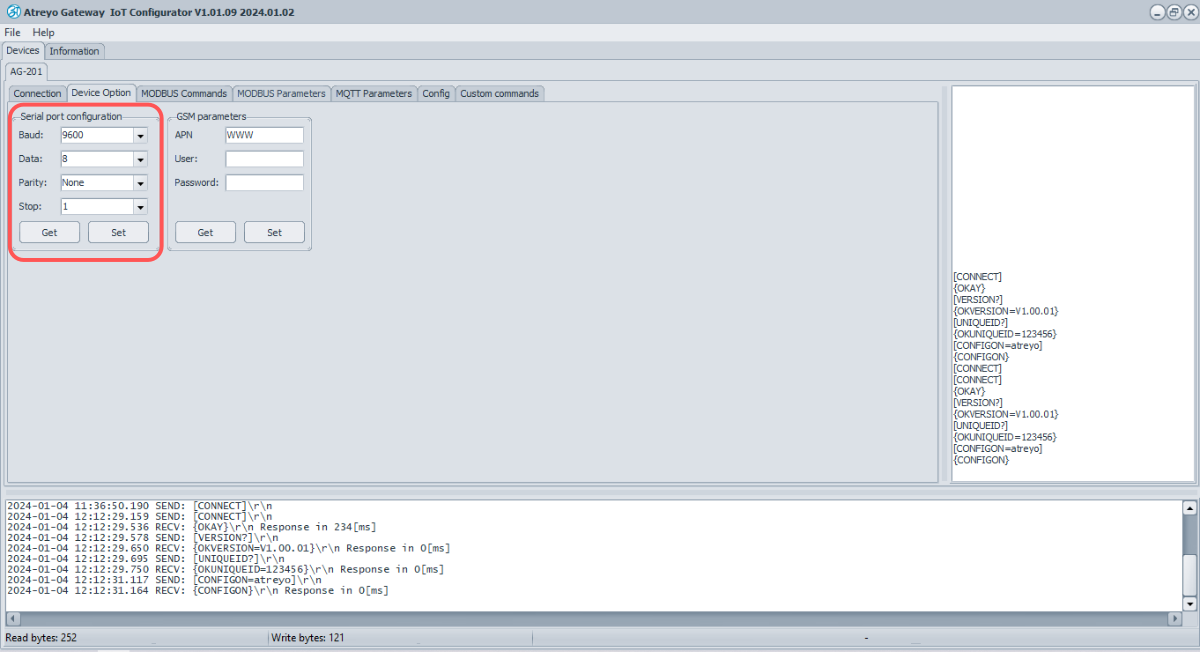](https://docs.atreyo.in/uploads/images/gallery/2025-02/uTAag-201-iot-configurator-configuration-serial.png) --- #### Beneral configuration 1. Reset the device parameters by selecting **Make default**. 2. Initiate a device restart by clicking on **Restart**. 3. Modify the password in the Device Password section; after entering the new password, click **Set Password**. 4. To apply and save these changes in the device, click **Config OFF.** 5. After configuring all parameters, remember to click **Config OFF**. 6. The device will automatically restart and operate based on the new configured parameters. #### Serial interface Go to Device option to view and configure serial parameter. To configure serial parameter: 1. Configure the b**audrate**, **parity**, **data bits** and **stop bits**. 2. Click "**Set**" to apply the chosen settings. 3. Click “**Get**”, to access the stored serial parameters from the device.| Fiels | Value | Comment |
| Baudrate | 2400 | 4800 |9600 |14400 | 19200 | 28800 | 33600 | 38400 | 57600 | 115200 | 230400 | 460800 |921600 | default: 9600 |
| Data | 8 | 9 | default: 8 |
| Parity | None | Odd | Even | default: None |
| Stop | 1 | 2 | default: 1 |
| Field | Value | Description |
| Slave ID | Integer\[1...255\] | Slave ID |
| Function code | Read Coils(1) | Read Discrete Input(2) | Read Holding Register(3) | Read Input Register(4) | Specifies the type of register being addressed by a Modbus request |
| Data structure | 8bit INT | 8bit UINT | 8bit HEX| 16bit INT |16bit UINT | 32bit float | 16bit HEX | 32bit HEX | Bool | Defines how read data will be stored |
| Start address | Integer \[0 – 65535\] | First Modbus register from which data will be read |
| Offset address | Integer | The starting address or position of a data element within a register or data block |
| Data length | Integer \[1 – 30\] | Number of Modbus registers that will be read during the request |
| Data length | Integer \[1 – 30\] | Number of Modbus registers that will be read during the request |
| Endian structure | 2bit data – ABCD | BADC | CDAB | DCBA 16bit data - AB | BA | Select endian structure of data type |
| Trigger | - | Not available now |
| riggering time | - | Not available now |
| Polling time | integer \[1..\]in sec; default: 60Sec | Interval at which requests are sent to the server device. |