AG-207
Industrial IoT Gateway AG-207 powered by the OpenWRT system. With OpenWRT, you gain access to an expansive repository of over 6000 ready-to-use applications, along with the freedom to integrate your own custom solutions. This cutting-edge gateway, AG-207 features RS485 and two digital inputs. Boasting enhanced built-in memory and RAM, the Gateway unlocks limitless programming potential, empowering your projects like never before.
Please read carefully before starting. Also read the product safety information.
General information
| Download technical specification | Technical Specification |
Model selection
Different Gateway models are available depending on the periphery availability and type.
| Model |
Cellular Network |
GNSS |
Internal memory |
||||
| GPRS | 3G |
LTR 4G |
5G |
Flash 64MB |
NAND 512MB |
||
| AG-207 | √ | √ | |||||
| AG-207-LT-IN | √ | √ | √ | √ | √ | ||
| AG-207-LT-EU | √ | √ | √ | √ | √ | ||
| AG-207-LT-GL | √ | √ | √ | √ | √ | √ | |
AG-207 is the basic variant of this model. Has a no cellular module.
The AG-207-LT-IN with LTE module. This module is to use in India.
The AG-207-LT-EU is the same as the base model except that it has a cellular module for use India and Europe.
The AG-207-LT-GL is a version with a module certified all over the world.
Hardware informations
The Gateway is made on one PCB, which is fitted to the aluminum housing. The housing is made of a thick, strong aluminum profile with two end plates also made from aluminum. The surface of the housing is finished by anodizing.
At the bottom of the housing there are slots through which DIN rail clamp or any other clamp can be mounted by t-nuts.
Top view dimensions

Side view dimensions

Connectors
Top view connectors and indicators


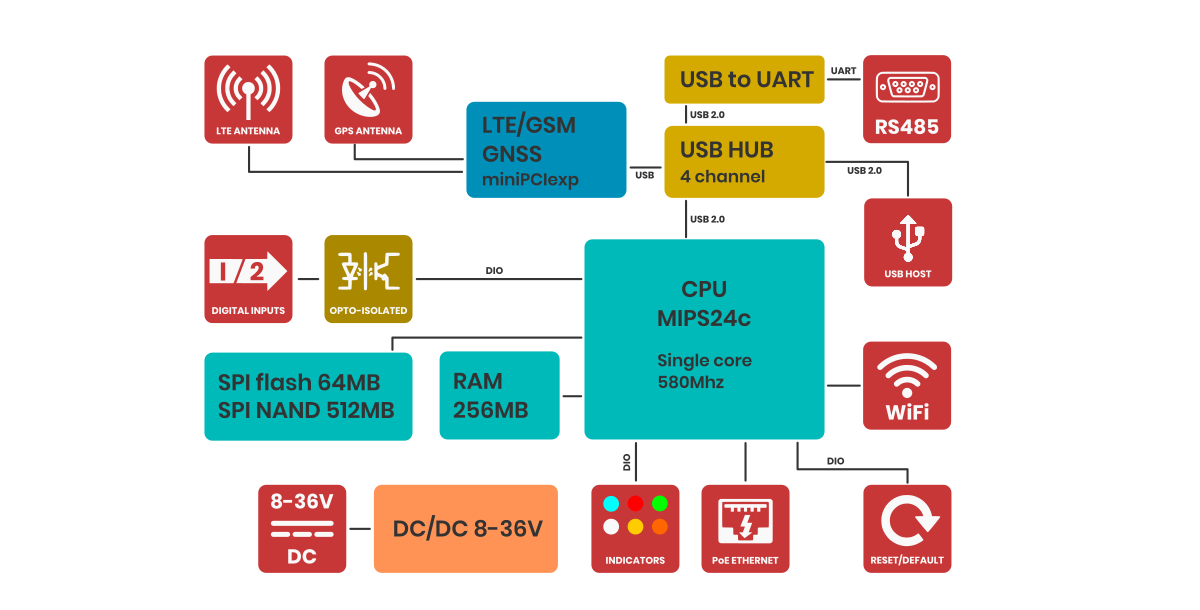
Block diagram
For a better understanding of the operation of the gateway, refer to the block diagram. Non-essential components have been omitted. Developers who program peripherals such as GPIOs, serial etc. will find information about them in the sections dedicated to such peripherals.
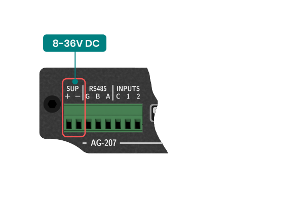
Power supply
The Gateway power supply range is 8-36V DC. First, connect the power supply according to the diagram. The Gateway is protected against reverse power connection. If the polarity is reversed, the Gateway will not start.

PoE
The Gateway can also be powered via PoE in the range of input power supply using unused pairs of wires in the LAN cable. Below is the pinout of the RJ45 socket.
| Pin number |
Function |
Comment |
| 1 |
RX+ | Data |
| 2 |
RX- | Data |
| 3 |
TX+ | Data |
| 4 |
DC+ | Power supply positive |
| 5 |
DC+ | Power supply positive |
| 6 |
TX- | Data |
| 7 |
DC- | Power supply negative |
| 8 |
DC- | Power supply negative |
LTE 4G modem
Generally, the Gateway supports all versions of Quectel MiniPCI express modems. However, you can use a third-party modem, as long as the signal outputs are compatible with those of the Quectel company. For use your LTE module, select model without LTE module installed. You also need to pay attention to the power supply to the LTE module should be 3.3V.
MiniPCI express pinout
Below is the description of the PCI express pinout used in the AG-702. Before installing anything other than the EC200U or EG25, be sure to check the pinout for compatibility. The LTE model is connected via a USB data bus.

GNSS
Device has wboded LTE modem along with GNSS function. In order to receive the GNSS signal, an antenna is required. There are two types of GNSS antennas: active gnss antenna and passive gnss antenna. The AG-702 supports both types of antennas, but in order for the active antenna to work properly, it is necessary to start powering the active antenna. To do this, you need to go to System > Custom Commands and select the command Turn GPS antenna to active mode.
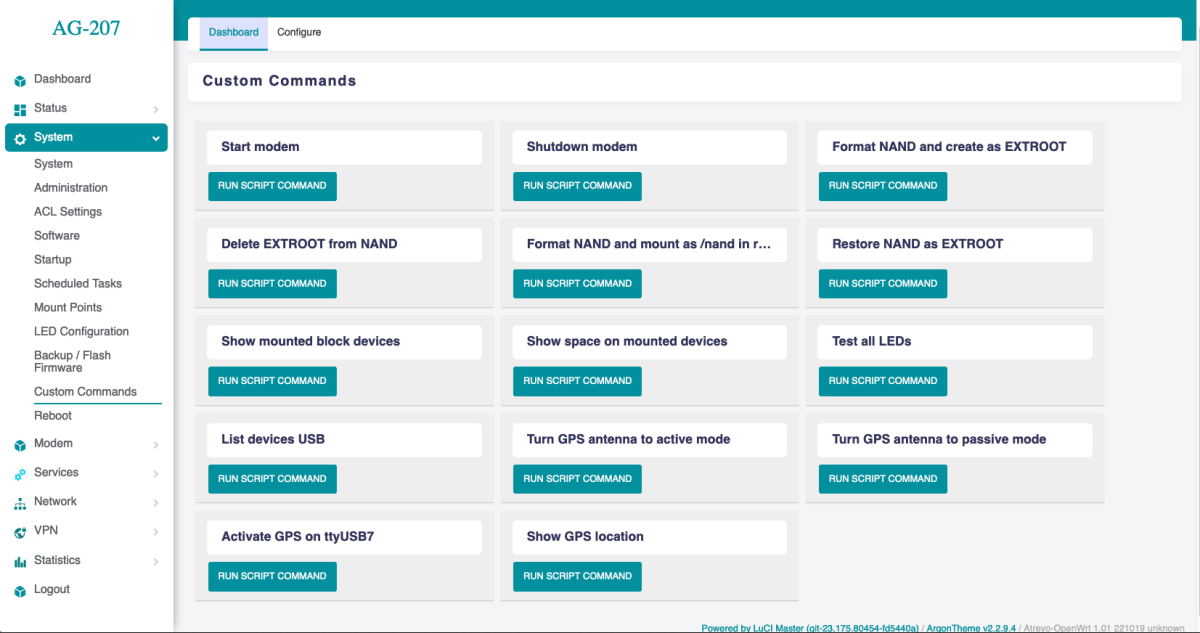
Also on this page, you can test whether the GNSS is working properly. To do so, you need to click Activate GPS on ttyUSB7 and then Show GPS location.
Ethernet
The gateway has one RJ45 ethernet ports with LED indicators. The speed of each is 100Mbps. Ethernet, IP and other settings are set on the Network > Interfaces page.
The default IP of ethernet is:
192.168.1.60
WiFi
The gateway has WiFi 2.4Ghz. By default, the WiFi is set as a hotspot and shares internet from Ethernet and from LTE via WiFi.
WiFi is used for remote configuration of the device. It does not have a long range, so it may not fully meet some requirements.
Serial Interface
The Gateway has one RS485.
RS485
The baudrate range for RS485 port (/dev/ttyUSB0) is 600 bps to 460800 bps. Note that with a longer cable, the maximum speed may drop. It is recommended to use special cables designed for RS485. The port is protected by high-power TVS diodes against electrical surges.
Digital Inputs
The Gateway has two digital inputs and one digital output.
Digital inputs
The digital inputs are completely independent optically isolated inputs that accept an input signal level of up to 30V DC. They have no common minus. They can be connected either with a common plus or minus. Can be controlled with open collector. They require to be powered. The range of the signal considered as a logical 1 is from 3.5V to the maximum input voltage.
Configuration Manual
Please read carefully before starting. Also read the product safety information.
This guide is updated regularly.
First start
After unpacking, the gateway is ready to use, but requires configuration to adapt to the required functions.
Power supply
First, connect the power supply according to the power supply information and to the diagram.
Opening inbuilt website
Through the WAN interface
To access the built-in website, connect the gateway by WAN to the local network and enter IP address in the address window of the browser. Please note that it may take some time from powering on to booting up the system. When the LEDs next to the RJ45 socket start flashing, after about 10 seconds the built-in website becomes available.
IP: 192.168.10.60
user name: root
password: root
Through the WiFi interface
By default, the gateway creates its own network with default ESSID "AG-207". The network is secured with default password "atreyo12". Connect to this network and enter the IP in the address bar of your browser.
IP: 192.168.1.1
user name: root
password: root

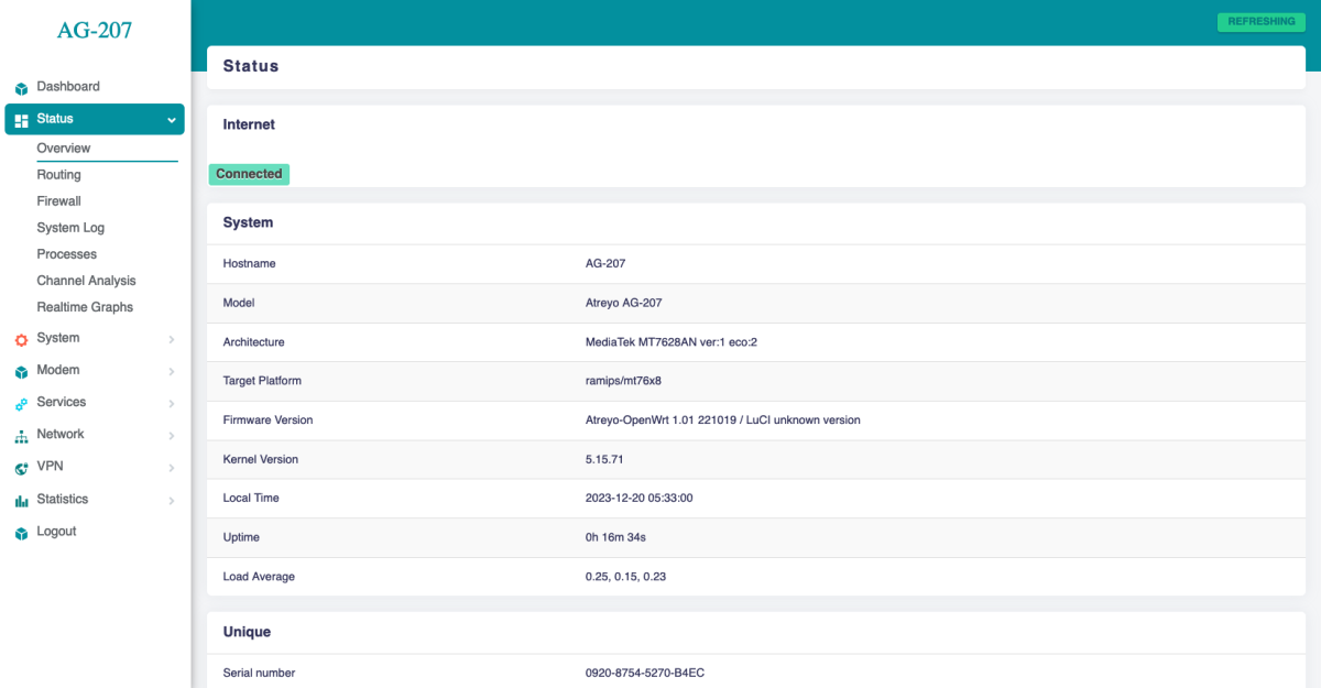
ASfter logging in, you are automatically taken to the dashboard page.
Password setting
To secure the gateway, change the default password. Set a password go to the system>administration page. To maintain security, it is recommended to use long and complex passwords.
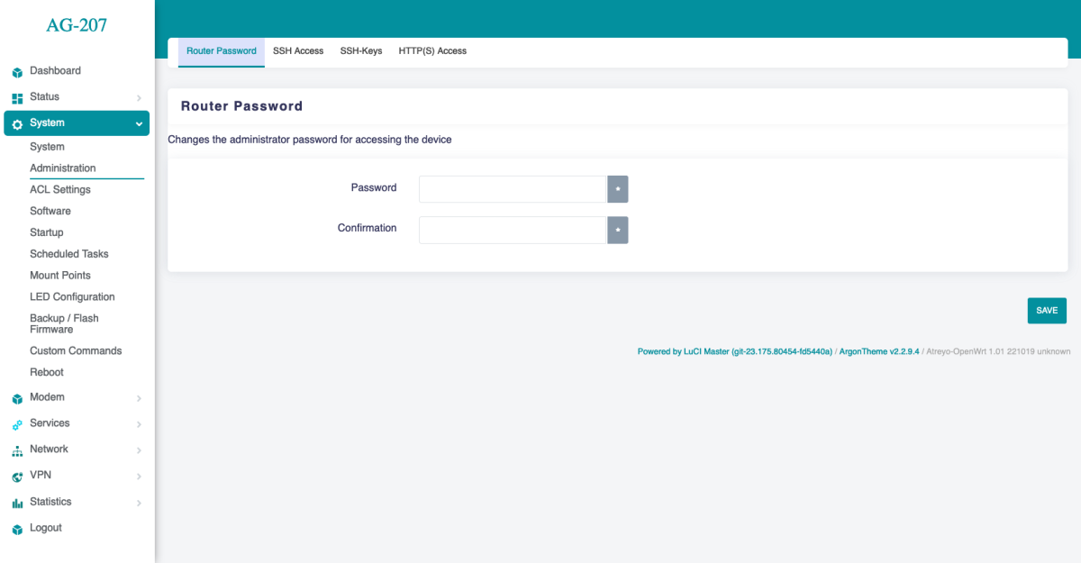
To maintain security, it is recommended to use long and complex passwords.
Cellular modem
Modem
The Gateway in its basic configuration is equipped with an LTE modem that also supports GPRS and SMS functions. Different modems were used depending on the model variant. Here is a table of models.
SIM card
The Gateway supports one microSIM card, both 1.8V and 3V. The card connector is tpush-pull type. When installing the SIM card, pay attention to the correct insertion of the card.
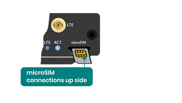
The card can be inserted the other way around and you can have the impression that you have inserted it correctly. So take a close look at the above drawing.
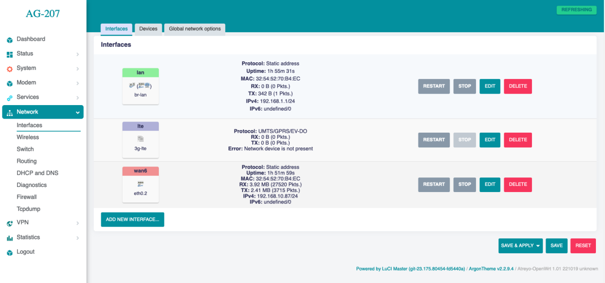
Using Cellular Network
To activate the LTE modem, go to Network > Interfaces and select the lte tab there.
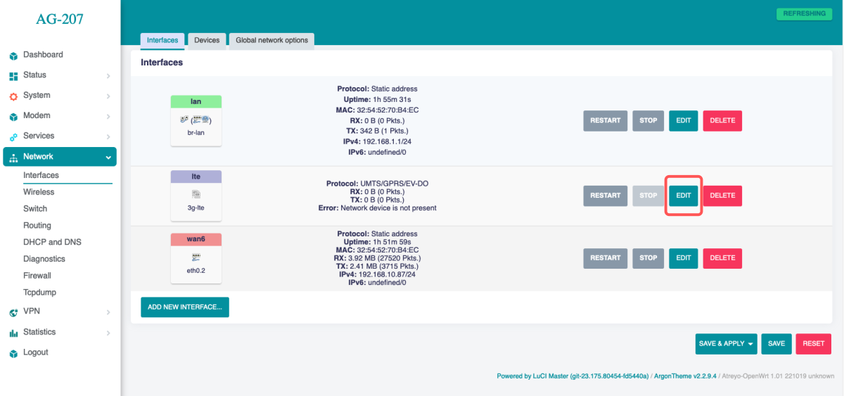
Mostly the network operator requires you to enter the APN, sometimes it also requires a username and password. Enter the required data and save.

Then go to System > Custom Commands and click on Start modem.
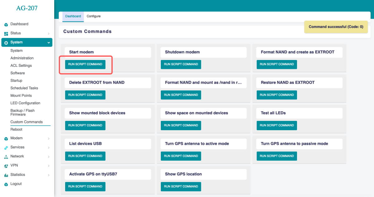
The modem will start up and connect to the Internet. To check if it is working properly and what the signal is, go to Modem > Information about 3G/4G/5G connection.

Cellular modem ON on start
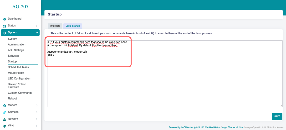
To make the gateway automatically connect to the Internet after startup, you need to add a modem startup in the System > Startup section under Local Startup, add a line before line 'exit 0'. /usr/commands/start_modem.sh. Then save the changes. After each reboot, the gateway will automatically start the modem.
SMS
To test the SMS operation, the gateway has an SMS interface installed. Under Modem > SMS Messages. There you can check sent and received SMS. Be sure to enter the phone number together with the country prefix, but without the + sign. The maximum number of characters is 160. The system does not support alphabets such as devanagari. The maximum number of messages in the inbox is 20.
For send SMS go to Send Message tab.
System statistics
The gateway has a built-in real-time statistics system under Status > Realtime Graphs and accurate statistics with selectable time range under Statistcis > Graph. You can check CPU load, memory usage, network load, etc.
Realtime Load
Statistics Interfaces
Statistics Memory
Statistics Processor
Statistics System Load
Modbus
The Gateway has a very advanced Modbus application with a convenient graphical interface. Below are the capabilities of the application:
- Modbus TCP/IP and Modbus RTU support.
- Any number of serial ports
- Support for external USB/serial interfaces
- JSON, TCP/IP and MQTT string formation
- Data logging in the event of no connection to a server
- Storage of all data in internal memory
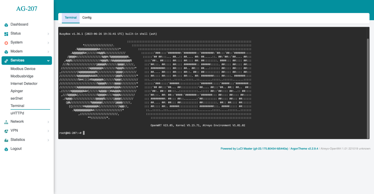
Using the terminal
The AG-702 has a built-in bash terminal. With it you can execute all commands in the OpenWRT system. To enter the terminal, go to the tools > terminal section on the built-in website. The default password is the same root/root.
Reset and default
Make factory default
To reset the system to factory settings, hold down the "Default/Reset" button for more than 5 seconds while the device is operational. During the factory reset, all LED indicators will light up for 2 seconds.
Reset device
To restart the gateway without disconnecting the power supply, press and hold the "Reset/Default" button for less than 5 seconds. During the restart, 4 LED indicators will light up for 1 second (IN-1, IN-2, RS485, RS232)
Do not hold the button for more than 5 seconds, as it will trigger the gateway to restore default settings.
Storage overlay
How to make a storage overlay
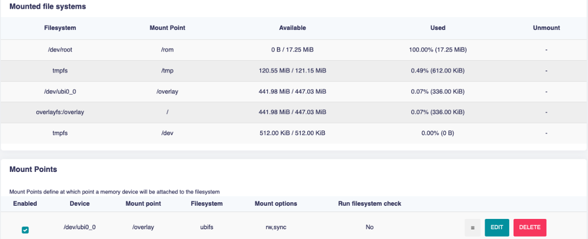
AG-207 has a 512MB NAND memory in addition to the 64MB FLASH memory. It is possible in a very simple way to increase the memory by extending the system partition to the so-called overlay.
To do this, go to the System > Custom Commands section and select Format NAND and create as EXTROOT. Then wait a while for the operation to complete when on boottom of page "Waiting for command to complete..." will close. The formatting process takes a few minutes.
Then, to verify, go to System > Mounting Points and see if we have the overlay done correctly.
You can also restore partitions to their previous state and format the NAND as data memory. For this isn custom command section click on Delete EXTROOT from NAND and after that Format NAND and mount as /nand in root file.
Applications
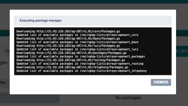
The gateway has the ability to install many ready-made applications. For this purpose, the gateway must be connected to the Internet. You need to go to System > Software. First click Update Lists...
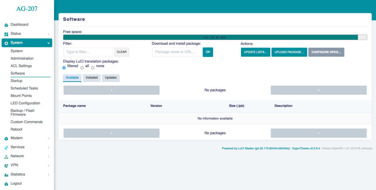
After waiting a while, the "Executing package manager" window will appear. You should click on Dismiss.
Then you can search for the application you are interested in by typing its name in the "Filter" window.
Application Installation
To install the application, click on install on the right side. Then if a "pop-up" appears then click dismiss.
Most of the time, applications are located in the Service tab after installation, although this is not the rule. After installation, you have to log out and login back in for the application to appear in the interface.
Local file installation
Also, you can install applications from a file on your computer. To do this, you need to click upload package.
Safety information
Operating environment
- The device is designed to be installed in clean, dust-free and insect-free places
- Operating temperature: -25 ~ 65°C (-13 ~ 149°F).
- Humidity range is 10% to 95% (non-condensing). Use the device in a dry environment.
- Away from heat sources and direct sunlight.
- It must not be exposed to acid fumes, salts and other chemicals.
- The device must not be used in places where there is a risk of gas explosion.
Use in inappropriate conditions may damage the device or shorten its life.
Electrical and power supply safety
- The device is powered with a voltage in the range of 8-36V. Voltage up to 24V is considered safe. Be especially careful when supplying them with higher voltages.
- Use only approved accessories
- Use the supplied power adapter or a good quality certified power adapter with the correct supply voltage range and sufficient power.
- Only use approved accessories like antenna etc.
Only a person with qualification and appropriate knowledge should install the device.
Malfunctioning and damaged device
- Do not disassemble the device.
- Only qualified personnel must service or repair the device or its accessories.
- If water or other liquid has got into the device, or if it looks mechanically damaged, do not connect the device, but take it to an authorized service center.
Radio frequency exposure
This device has been designed and manufactured not to exceed radio frequency energy emission limits set by regulatory agencies. To comply with RF exposure guidelines, the device must be used at least 20 cm away from a person's body. Failure to follow these instructions may result in exceeding the applicable RF exposure limits. This only applies to models with a built-in LTE modem.
What to do and what not to do
- You are solely responsible for the use of the device and any consequences of its use.
- Do not store or use the device in harsh environments such as dust, gases, oils, chemical vapors and damp places.
- Do not throw the device and its accessories. Handle with care.
- The device heats up during operation. Ensure proper ventilation.
- If you need to dispose of your device, check your local regulations for recycling and disposal of electronics.
- Route power, Ethernet, and antenna cables properly so that they cannot be accidentally pulled out.
- The device should be used and kept away from small children.