AG-702
The AG-702 is multipurpose Industrial IoT Gateway based on OpenWRT system. Open WRT support more than 6000 ready applications in our repository. AG-702 has opto-isolated RS485 and RS232, two digital inputs and one relay output. Support Modbus RTU and Modbus TCP/IP. Dual Ethernet, isolated interfaces wide power supply range up to 60V is perfect choice for industrial control systems.
Please read carefully before starting. Also read the product safety information.
- General information
- Configuration Manual
- Modbus Master
- IoT platform integration
- Firmware update
- Safety information
General information
| Download technical specification | Technical Specification |
Model selection
Different Gateway models are available depending on the periphery availability and type.
| Model |
Cellular Network |
GNSS |
Internal memory |
||||
| GPRS | 3G |
LTE 4G |
5G |
Flash 64MB |
NAND 512MB |
||
| AG-702-V48 | √ | √ | |||||
| AG-702-LT-IN-V48 | √ | √ | √ | √ | √ | ||
| AG-702-LT-EU-V48 | √ | √ | √ | √ | √ | ||
| AG-702-LT-GL-V48 | √ | √ | √ | √ | √ | √ | |
Hardware informations
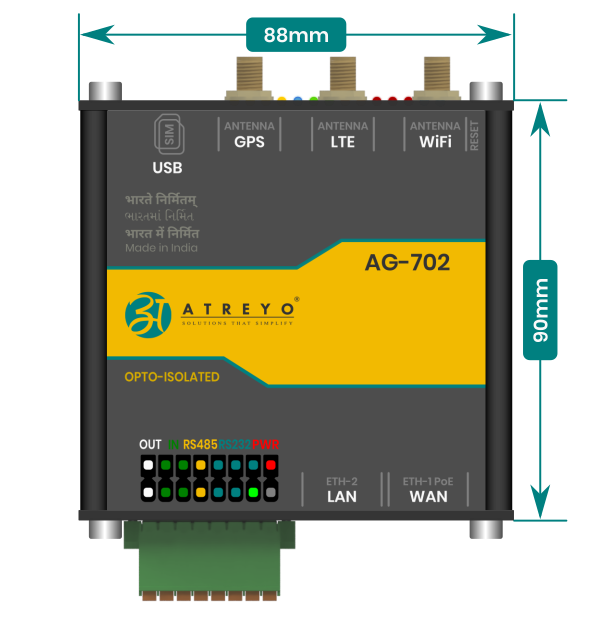
The Gateway is made on one PCB, which is fitted to the aluminum housing. The housing is made of a thick, strong aluminum profile with two end plates also made from aluminum. The surface of the housing is finished by anodizing.
At the bottom of the housing there are slots through which DIN rail clamp or any other clamp can be mounted by t-nuts.
Top view dimensions
Side view dimensions
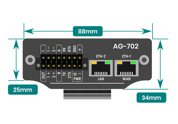
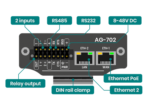
Connectors
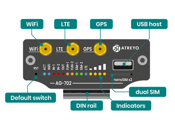
Top view connectors and indicators
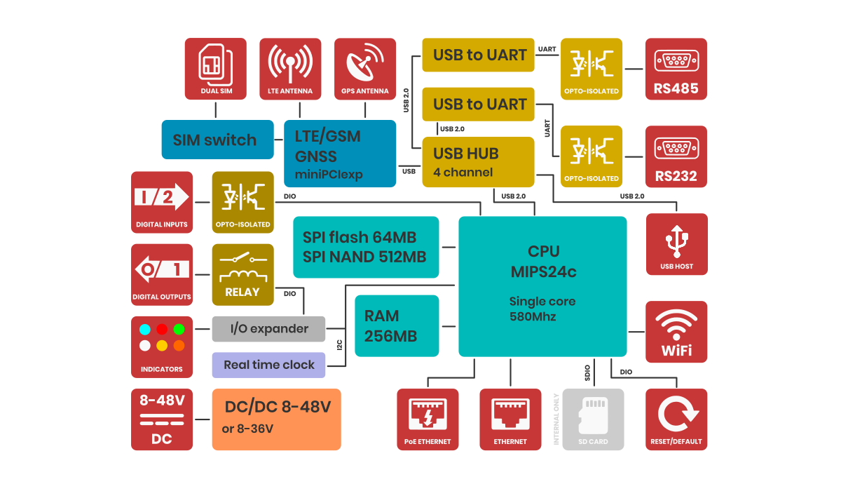
Block diagram
For a better understanding of the operation of the gateway, refer to the block diagram. Non-essential components have been omitted. Developers who program peripherals such as GPIOs, serial etc. will find information about them in the sections dedicated to such peripherals.
Power supply
The Gateway power supply range is 8-48V DC (version V48). You need to connect the gate according to the inscriptions at the main connector. The Gateway is protected against reverse power connection. If the polarity is reversed, the Gateway will not start.
PoE
The Gateway can also be powered via PoE in the range of input power supply using unused pairs of wires in the LAN cable. Below is the pinout of the RJ45 socket.
| Pin number |
Function |
Comment |
| 1 |
RX+ | Data |
| 2 |
RX- | Data |
| 3 |
TX+ | Data |
| 4 |
DC+ | Power supply positive |
| 5 |
DC+ | Power supply positive |
| 6 |
TX- | Data |
| 7 |
DC- | Power supply negative |
| 8 |
DC- | Power supply negative |
LTE 4G modem
Generally, the Gateway supports all versions of Quectel MiniPCI express modems. However, you can use a third-party modem, as long as the signal outputs are compatible with those of the Quectel company. For use your LTE module, select model without LTE module installed. You also need to pay attention to the power supply to the LTE module should be 3.3V.
Mobile network signal strength is also displayed on 4 LED indicators.
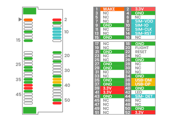
MiniPCI express pinout
Below is the description of the PCI express pinout used in the AG-702. Before installing anything other than the EC200U or EG25, be sure to check the pinout for compatibility. The LTE model is connected via a USB data bus.
GNSS
Device has wboded LTE modem along with GNSS function. In order to receive the GNSS signal, an antenna is required. There are two types of GNSS antennas: active gnss antenna and passive gnss antenna. The AG-702 supports both types of antennas, but in order for the active antenna to work properly, it is necessary to start powering the active antenna. To do this, you need to go to System > Custom Commands and select the command Turn GPS antenna to active mode.
Also on this page, you can test whether the GNSS is working properly. To do so, you need to click Activate GPS on ttyUSB7 and then Show GPS location.
Ethernet
The gateway has two RJ45 ethernet ports with LED indicators. The speed of each is 100Mbps. By default, Ethernet-1 is configured as a WAN port and Ethernet-2 is configured as a LAN port. Ethernet-1 supports PoE on free RJ45 pairs.
The default IP of ethernet:
Eth-1: DHCP
Eth-2: 192.168.1.1
WiFi
The gateway has WiFi 2.4Ghz. By default, the WiFi is set as a hotspot and shares internet from Ethernet and from LTE via WiFi.
WiFi is used for remote configuration of the device. It does not have a long range, so it may not fully meet some requirements.
RTC
The gateway has a built-in RTC with battery packup power. The battery used is CR1220 size.
All gateways that are exported due to transportation regulations are sold without batteries.
Serial Interface
The Gateway has two serial ports. One RS232 and one RS485. Both ports are optically isolated from the main computer circuit, but are not isolated from each other. In addition to insulation, they are also protected against surges.
RS232
The RS232 port includes CTS and RTS signals in addition to TX and RX signals. The baudrate range for the RS232 port is 300bps to 230400bps . The port is protected by high-power TVS diodes against electrical surges.
RS485
The baudrate range for RS485 port is 600 bps to 460800 bps. Note that with a longer cable, the maximum speed may drop. It is recommended to use special cables designed for RS485. The port is protected by high-power TVS diodes against electrical surges.
Digital I/O
The Gateway has two digital inputs and one digital output.
Digital inputs
The digital inputs are completely independent optically isolated inputs that accept an input signal level of up to 30V DC. They have no common minus. They can be connected either with a common plus or minus. Can be controlled with open collector. They require to be powered. The range of the signal considered as a logical 1 is from 3.5V to the maximum input voltage.
Digital output
The digital output is realized on a relay whose load capacity is 3A. The maximum voltage is 160V AC and 30DC. The output is only in normal open format (NO).
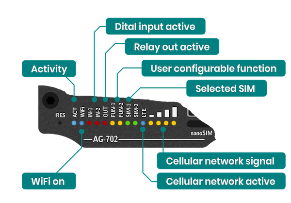
LED indicators
The AG-702 gateway has fourteen indicators on the front panel. By default, they are programmed to perform certain functions, but they are all controlled by the processor and knowing the OpenWRT system well, change their functions.
Configuration Manual
Please read carefully before starting. Also read the product safety information.
First start
After unpacking, the gateway is ready to use, but requires configuration to adapt to the required functions.
Power supply
First, connect the power supply according to the power supply information.
Opening inbuilt website
Through the WAN interface
To access the built-in website, connect the gateway by WAN to the local network and enter the DHCP assigned IP address in the address window of the browser. Please note that it may take some time from powering on to booting up the system. When the LEDs next to the RJ45 socket start flashing, after about 10 seconds the built-in website becomes available.
user name: root
password: root
Through the LAN interface
Connect the ETH2 directly to the computer and enter in the address window of the browser default IP of Gateway.
IP: 192.168.1.1
user name: root
password: root
Through the WiFi interface
By default, the gateway creates its own network with default ESSID "AG-702". The network is secured with default password "atreyo12".
Connect to this network and enter the IP in the address bar of your browser.
IP: 192.168.1.1
user name: root
password: root

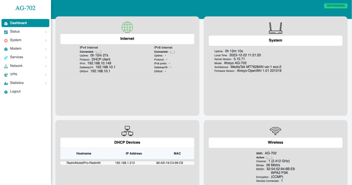
ASfter logging in, you are automatically taken to the dashboard page.
Password setting
At the top there is a message that no password has been set.
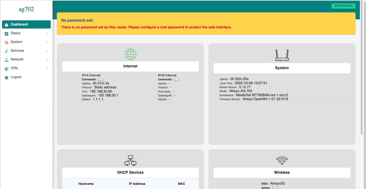
Set a password on the system>administration page:
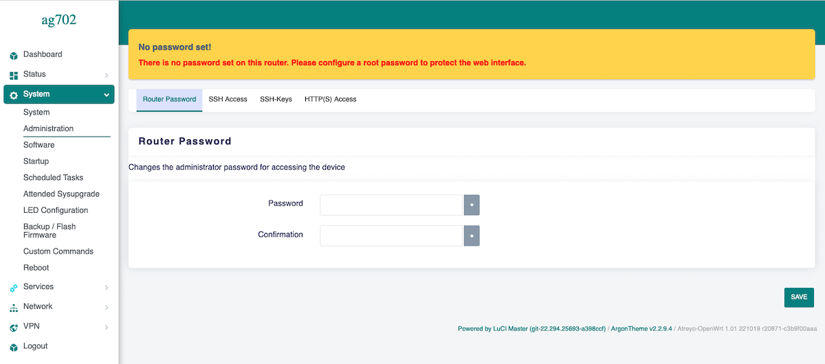
To maintain security, it is recommended to use long and complex passwords.
Cellular modem
Modem
The Gateway in its basic configuration is equipped with an LTE modem that also supports GPRS and SMS functions. Different modems were used depending on the model variant. Here is a table of models.
SIM card
The Gateway supports two nano SIM cards, both 1.8V and 3V. The card connector is tray type. When installing the SIM card, pay attention to the correct insertion of the card. The used SIM card tray is designed so that the card sticks to the tray. This make easily insert the SIM regardless of the position of the Gateway
Using Cellular Network
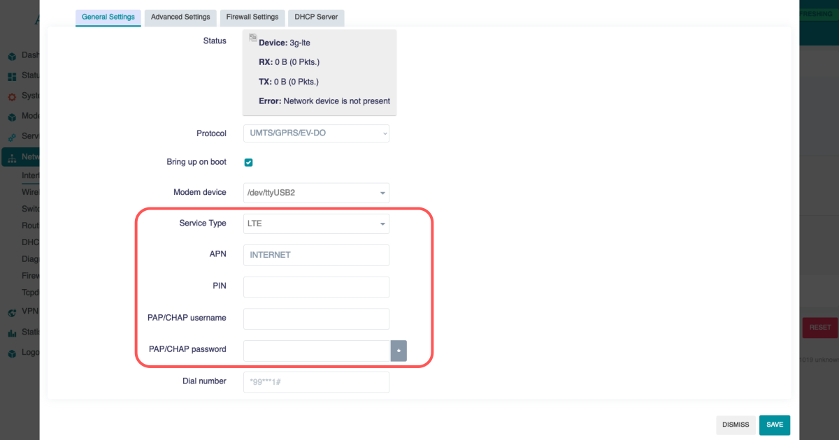
To activate the LTE modem, go to Network > Interfaces and select the lte tab there.
Mostly the network operator requires you to enter the APN, sometimes it also requires a username and password. Enter the required data and save.
Then go to System > Custom Commands and click on Start modem with SIM1/Start modem with SIM2. Depending on which SIM card you want to start.
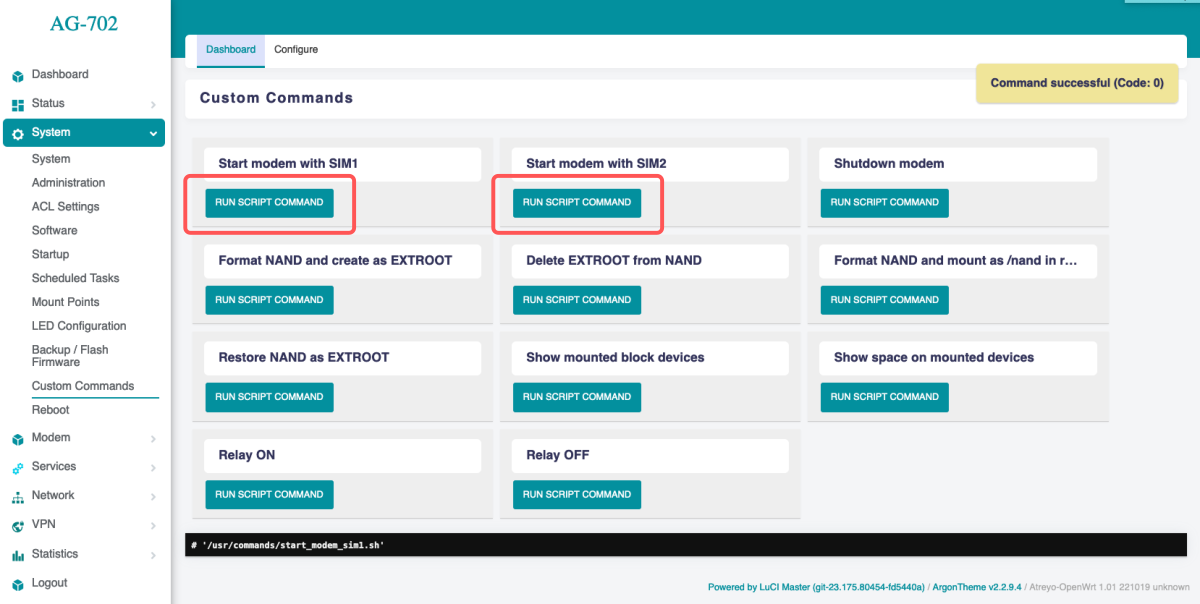
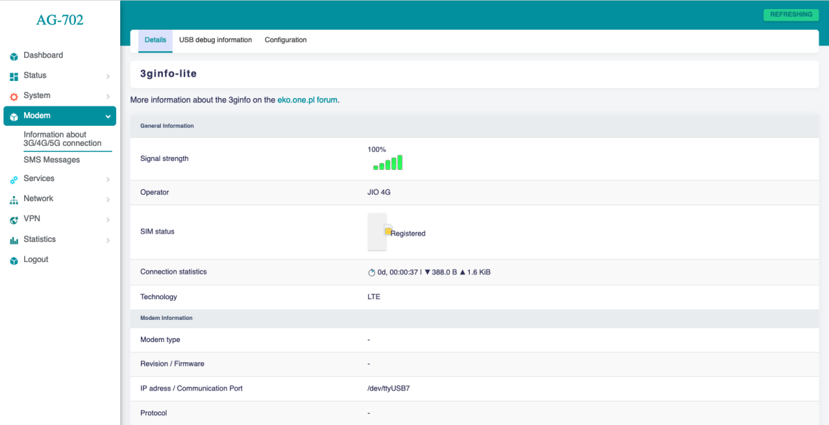
The modem will start up and connect to the Internet. To check if it is working properly and what the signal is, go to Modem > Information about 3G/4G/5G connection. When the modem starts up, the LEDs showing the signal strength will also light up. This makes it easy to see the signal strength in a particular location.
Cellular modem ON on start
To make the gateway automatically connect to the Internet after startup, you need to add a modem startup in the System > Startup section under Local Startup, add a line before line 'exit 0'.
/usr/commands/start_modem_sim1.sh or /usr/commands/start_modem_sim2.sh. Then save the changes. After each reboot, the gateway will automatically start the modem with the selected SIM card.
SMS
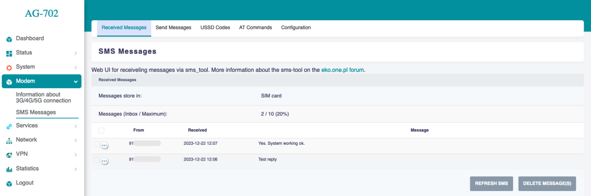
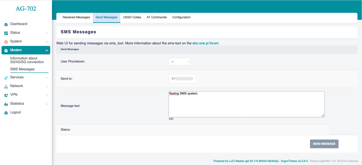
To test the SMS operation, the gateway has an SMS interface installed. Under Modem > SMS Messages. There you can check sent and received SMS. Be sure to enter the phone number together with the country prefix, but without the + sign. The maximum number of characters is 160. The system does not support alphabets such as devanagari. The maximum number of messages in the inbox is 20.
For send SMS go to Send Message tab.
System statistics
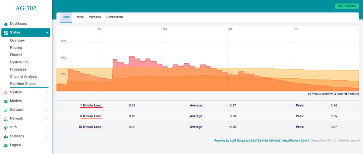
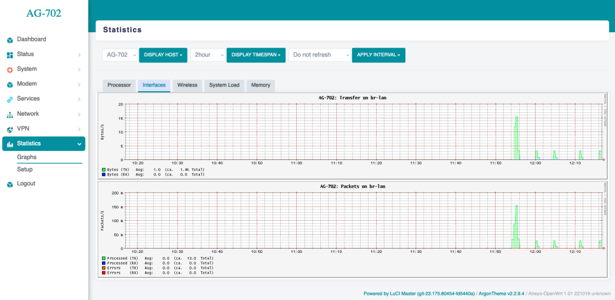
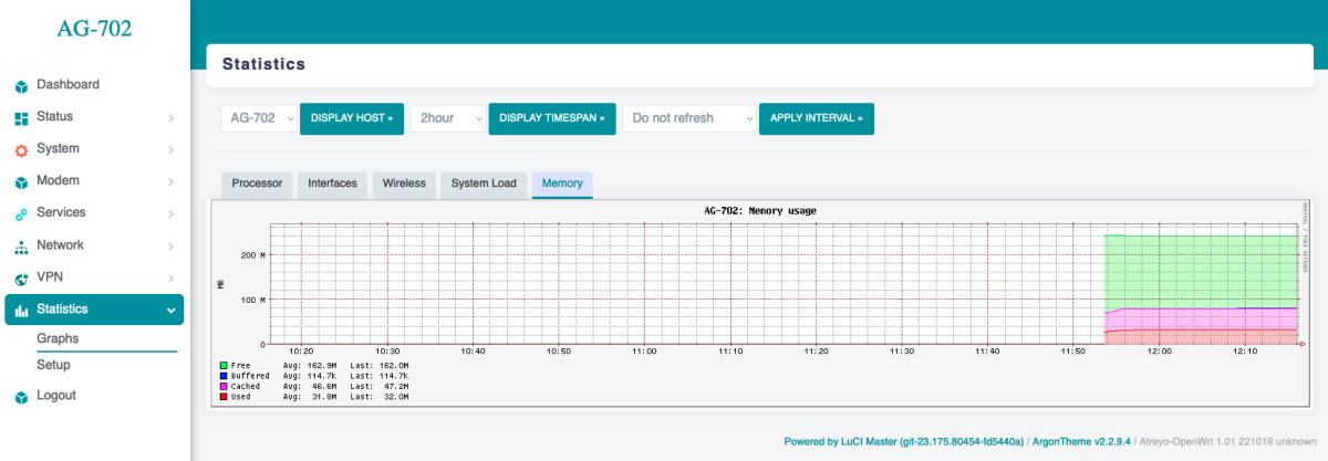
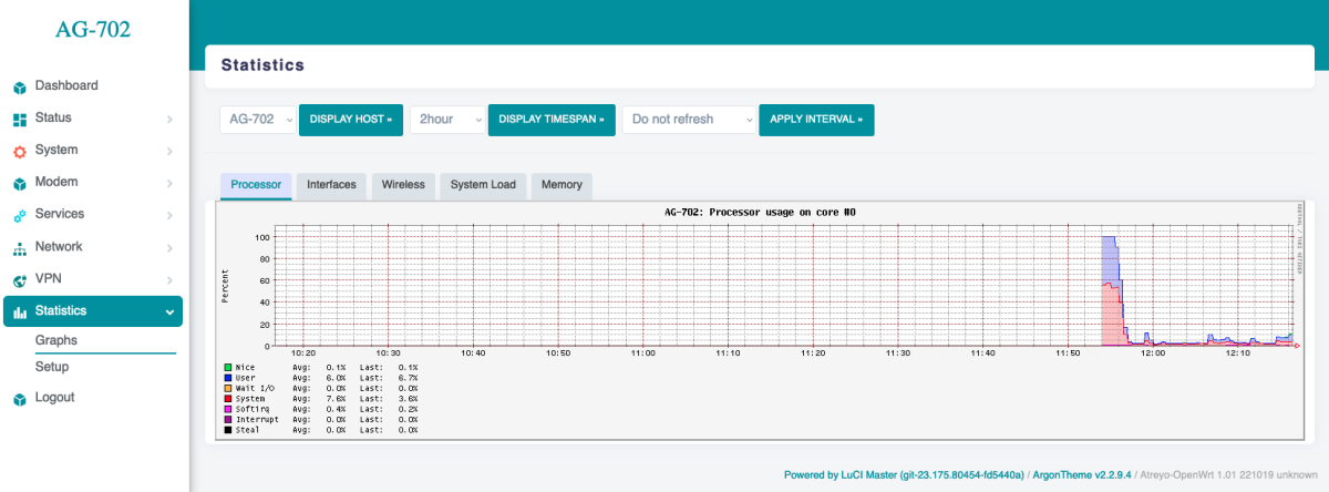
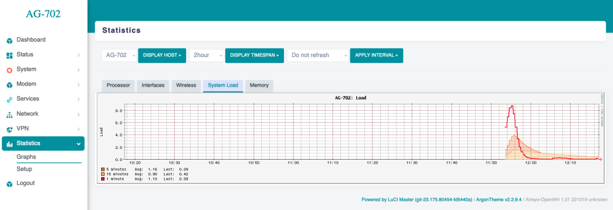
The gateway has a built-in real-time statistics system under Status > Realtime Graphs and accurate statistics with selectable time range under Statistcis > Graph. You can check CPU load, memory usage, network load, etc.
Realtime Load
Statistics Interfaces
Statistics Memory
Statistics Processor
Statistics System Load
Modbus
The Gateway has a very advanced Modbus application with a convenient graphical interface. Below are the capabilities of the application:
- Modbus TCP/IP and Modbus RTU support.
- Any number of serial ports
- Support for external USB/serial interfaces
- JSON, TCP/IP and MQTT string formation
- Data logging in the event of no connection to a server
- Storage of all data in internal memory
A detailed guide to Modbus configuration is available here.
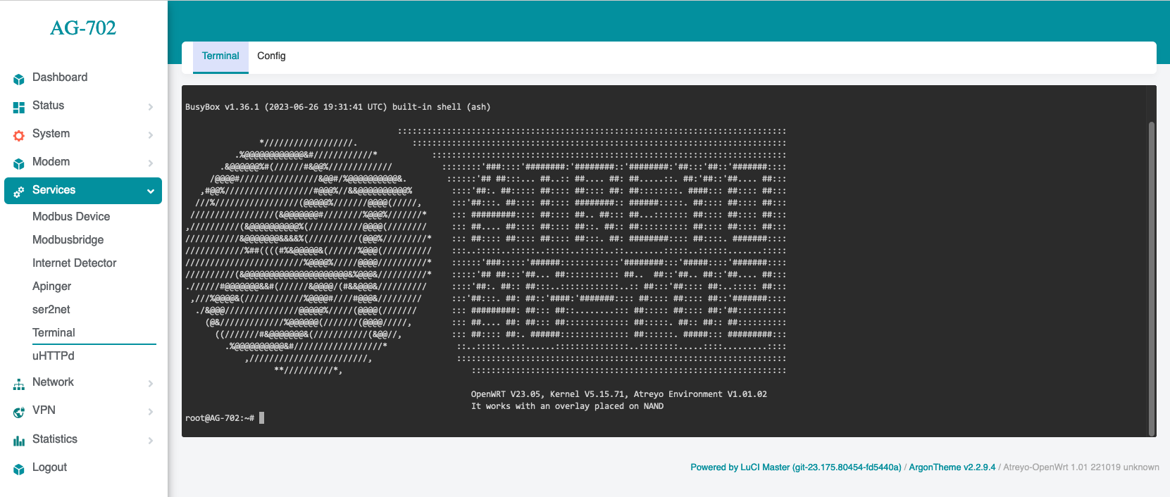
Using the terminal
The AG-702 has a built-in bash terminal. With it you can execute all commands in the OpenWRT system. To enter the terminal, go to the tools > terminal section on the built-in website. The default password is the same root/root.
Reset and default
Make factory default
To reset the system to factory settings, hold down the "Default/Reset" button for more than 5 seconds while the device is operational. During the factory reset, all LED indicators will light up for 2 seconds.
Reset device
To restart the gateway without disconnecting the power supply, press and hold the "Reset/Default" button for less than 5 seconds. During the restart, 4 LED indicators will light up for 1 second (IN-1, IN-2, RS485, RS232)
Do not hold the button for more than 5 seconds, as it will trigger the gateway to restore default settings.
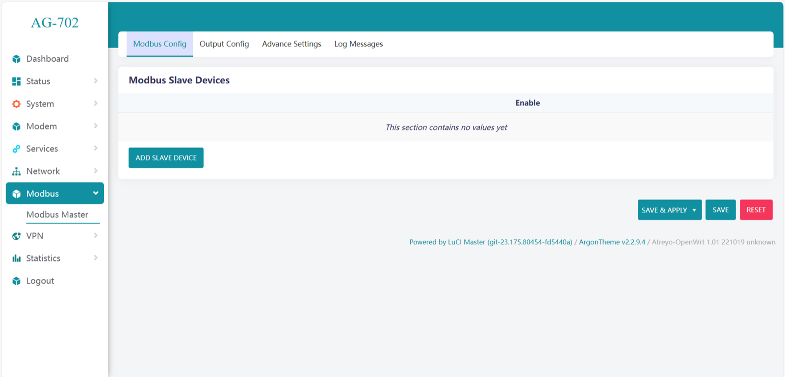
Modbus Master
Modbus Master is an application that allows full operation of devices connected to the gateway over Modbus RTU and Modbus TCP/IP. Also, the application allows sending data to the server via MQTT, TCP/IP JSON and saving to storage.
Configuration of Modbus Master
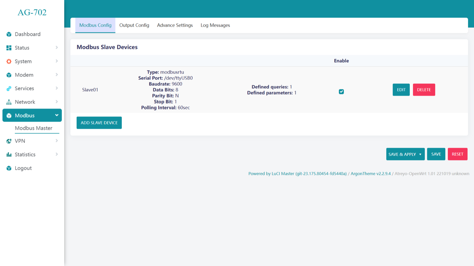
To open Modbus master, go to Modbus > Modbus Master
Add Slave Device in Modbus Slave Devices
Enter a slave device name of your choice & Select communication protocol.
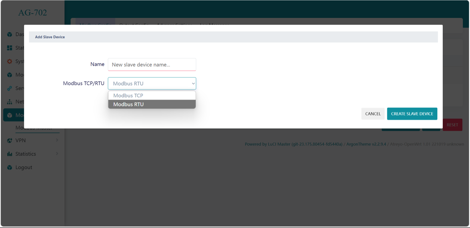
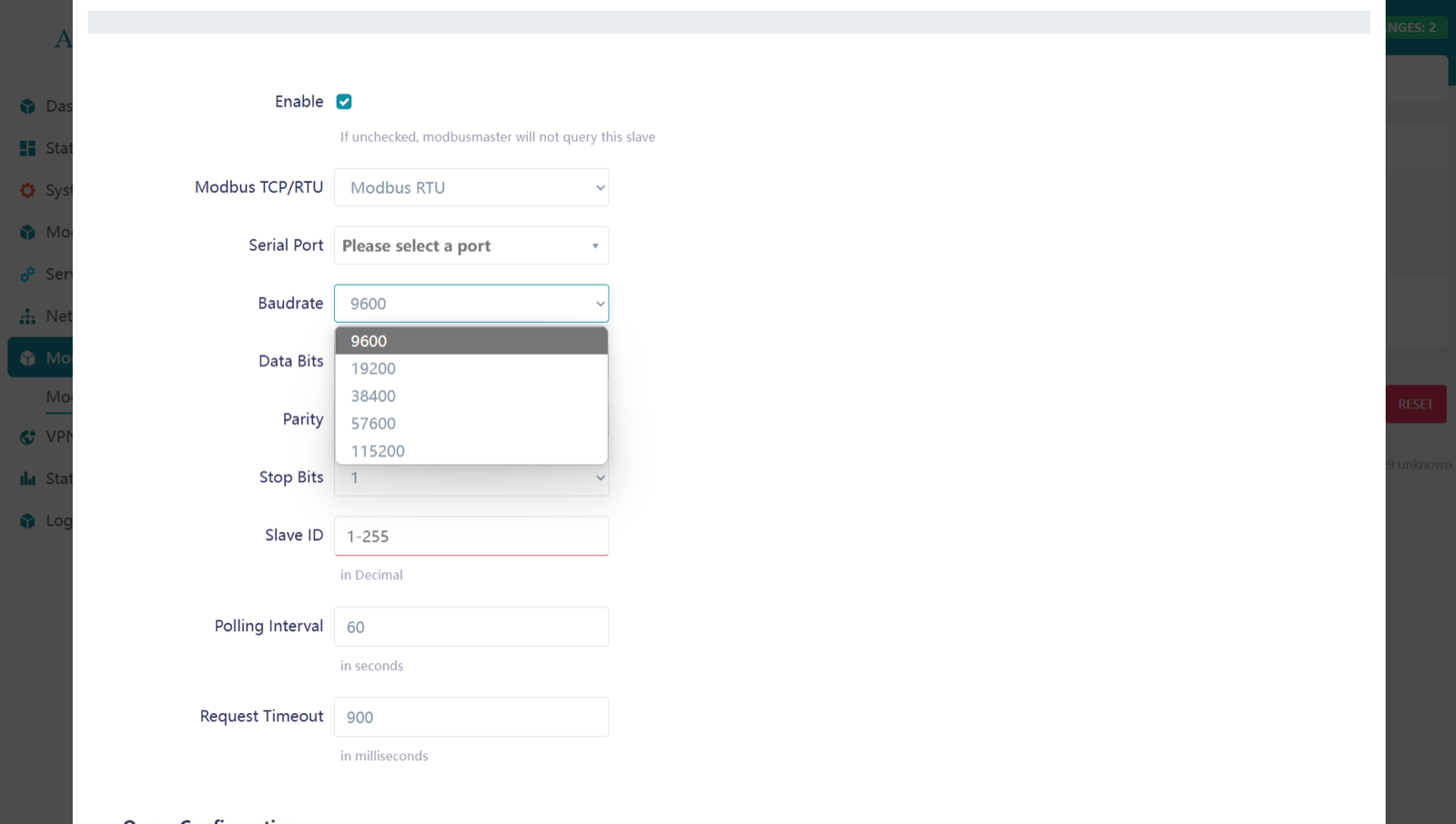
Modbus RTU
Need to enter the serial port configuration according to the slave device. Here in AG-702 serial port USB0 is for RS232 & USB1 is for RS485. If you use a USB to serial converter, you can customize the port name by adding another port.
/dev/ttyUSB0 = RS232
/dev/ttyUSB1 = RS485
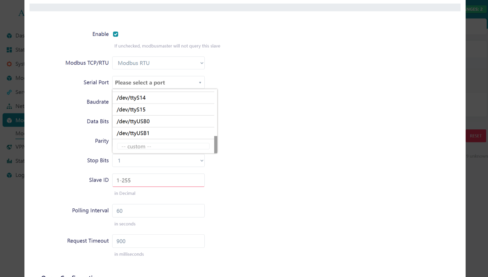
Change the baud-rate according to your slave device requirement. In Modbus RTU 9600 baud-rate is most common used.
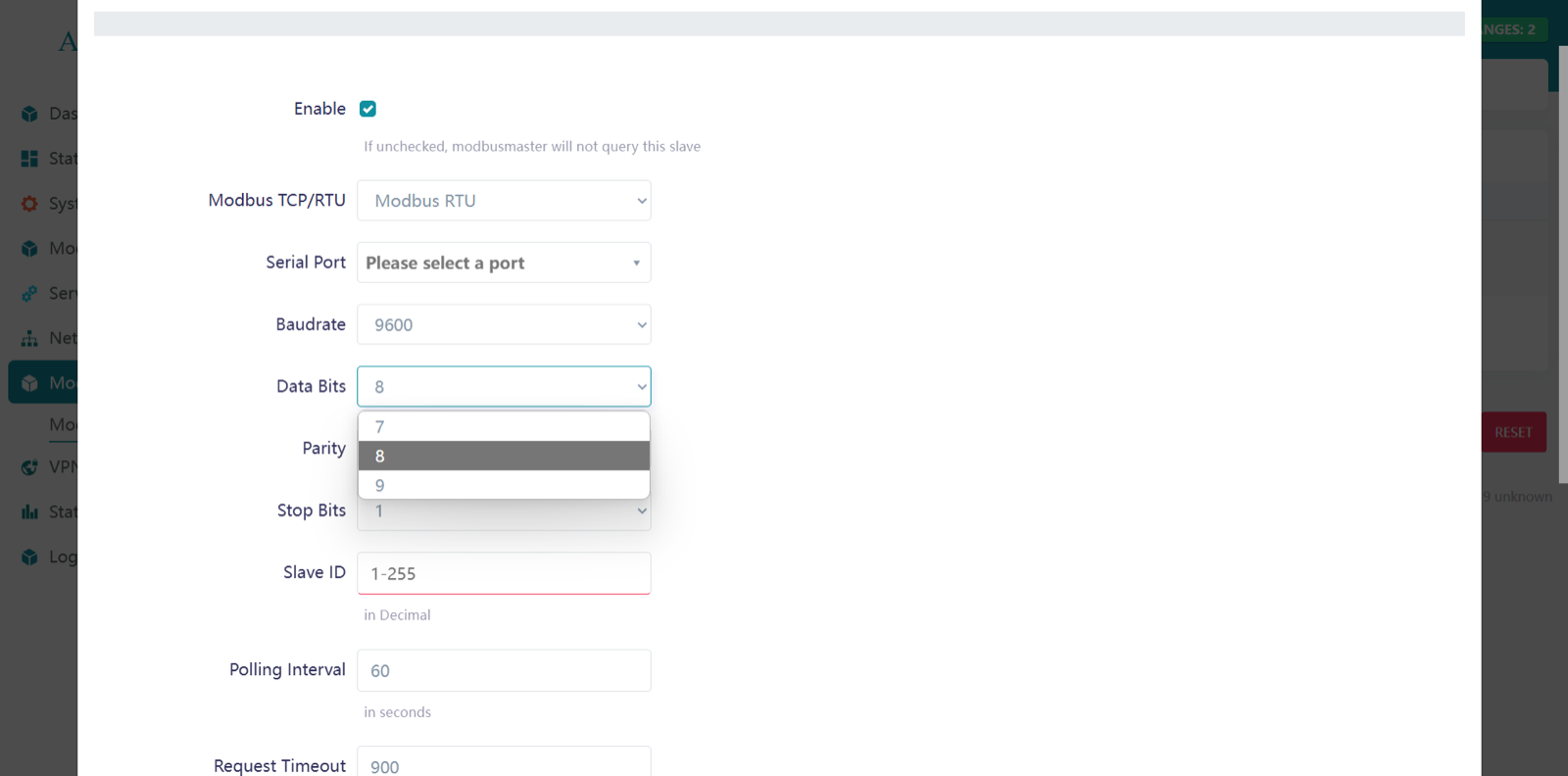
Data bits are used to represent each character or data unit in a communication protocol. Select the appropriate setting.
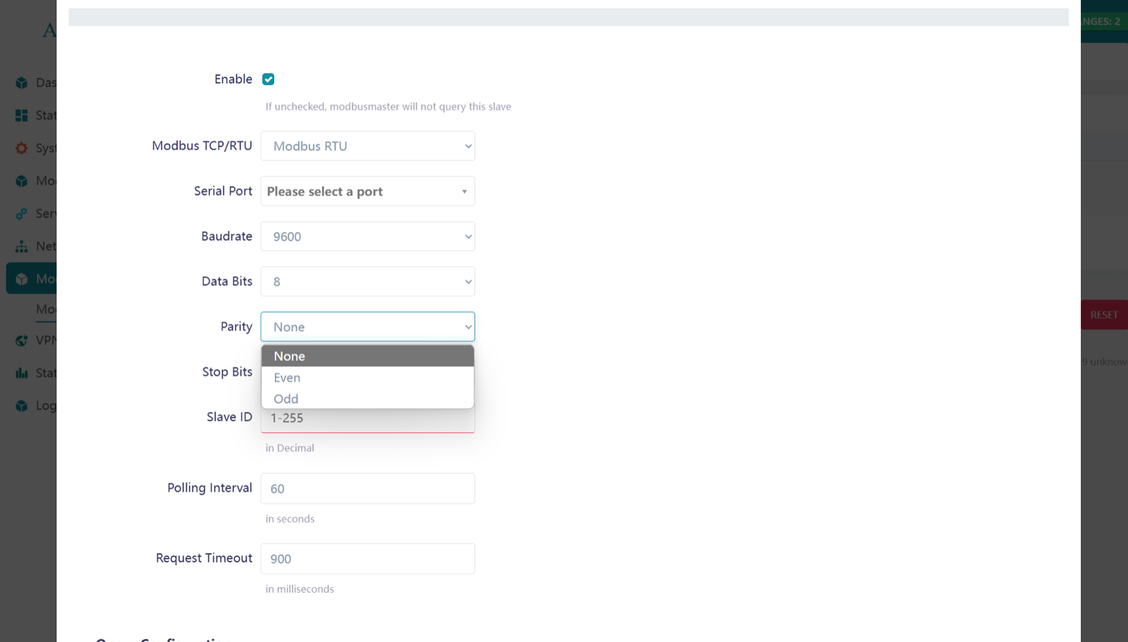
Parity is an error-checking mechanism to detect data transmission errors. Most devices use the None option.
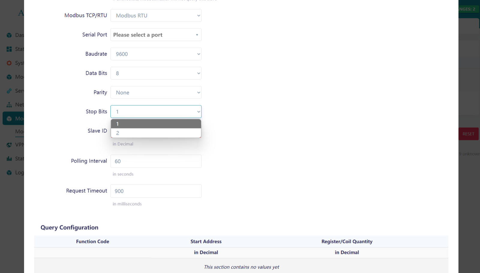
A stop bit signals the end of a data frame, helping the receiver recognize when one byte is complete.
- 1 Stop Bit: For stable connections and higher speed.
- 2 Stop Bits: For increased reliability or when devices need more processing time.
Select the option according to the slave device.
Modbus TCP/IP
In Modbus TCP/IP, only the IP address and port number (typically 502) are required for communication.

Modbus slave
After entering these parameters, the next configuration steps are the same for both Modbus TCP and Modbus RTU.
You should enter the slave ID (1-255), polling interval, and request timeout according to your requirements.
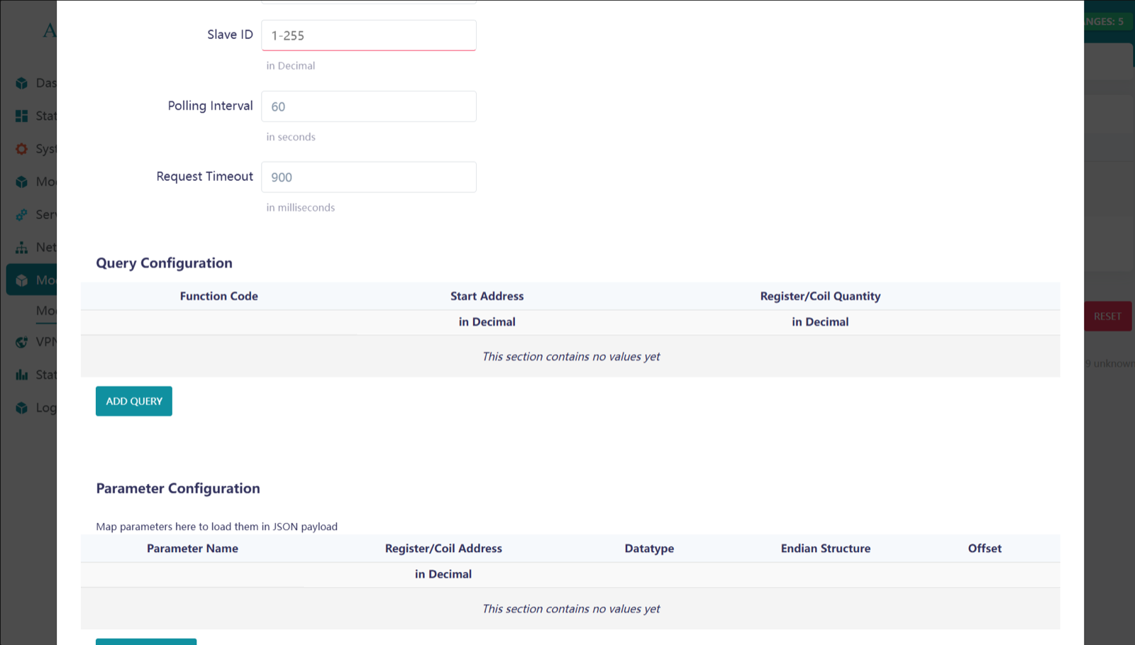
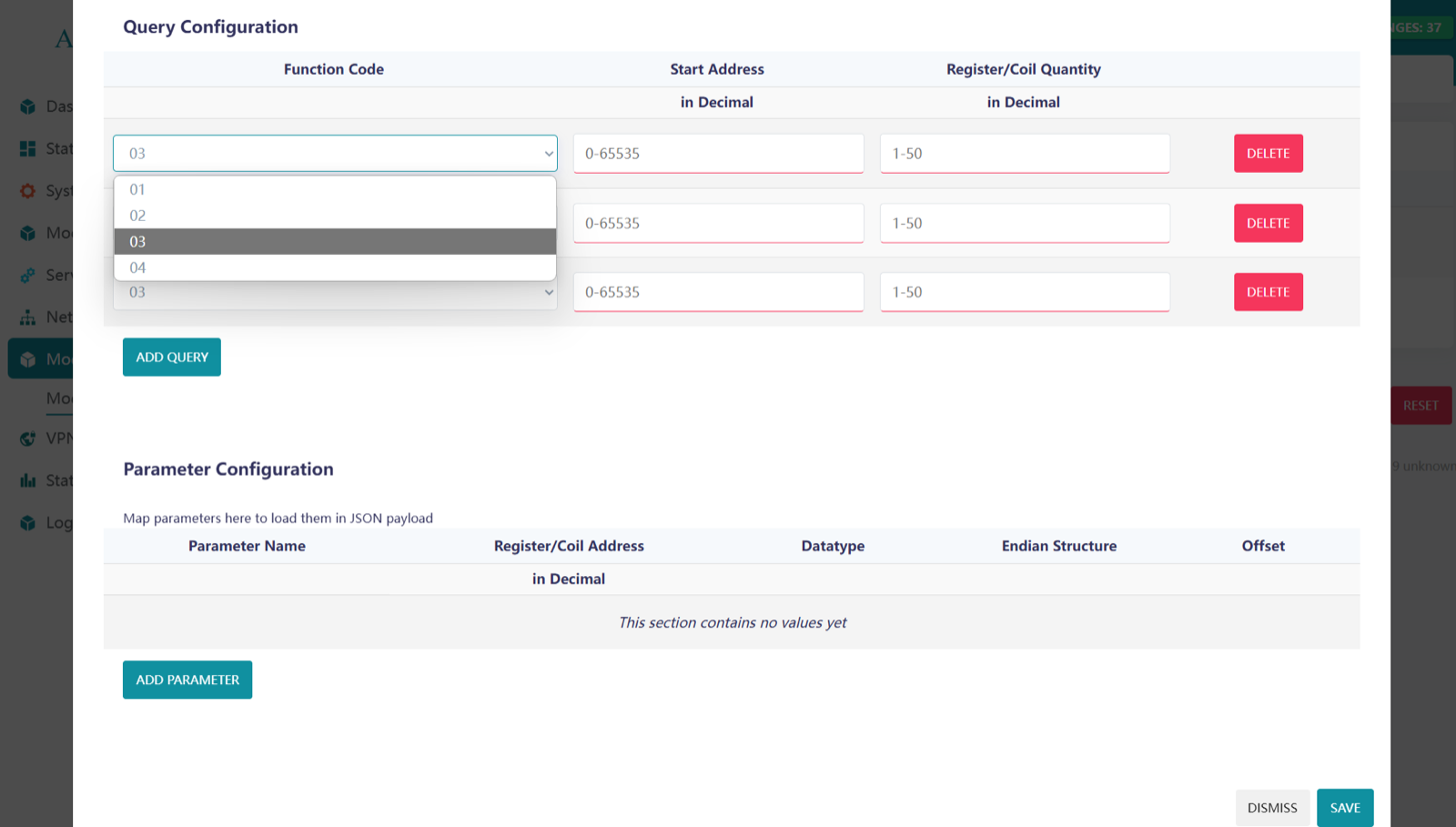
Query Configuration
To make a Query, click on ADD QUERY
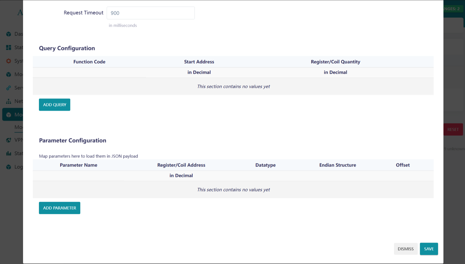
Enter the Function code, Start Address, Register/Coil number as per the Slave documentation or instruction. Here 1-50 register/coil quantity is supported.
Parameter Configuration
Enter and select the option as per your requirement.
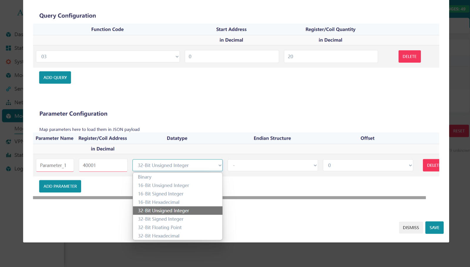
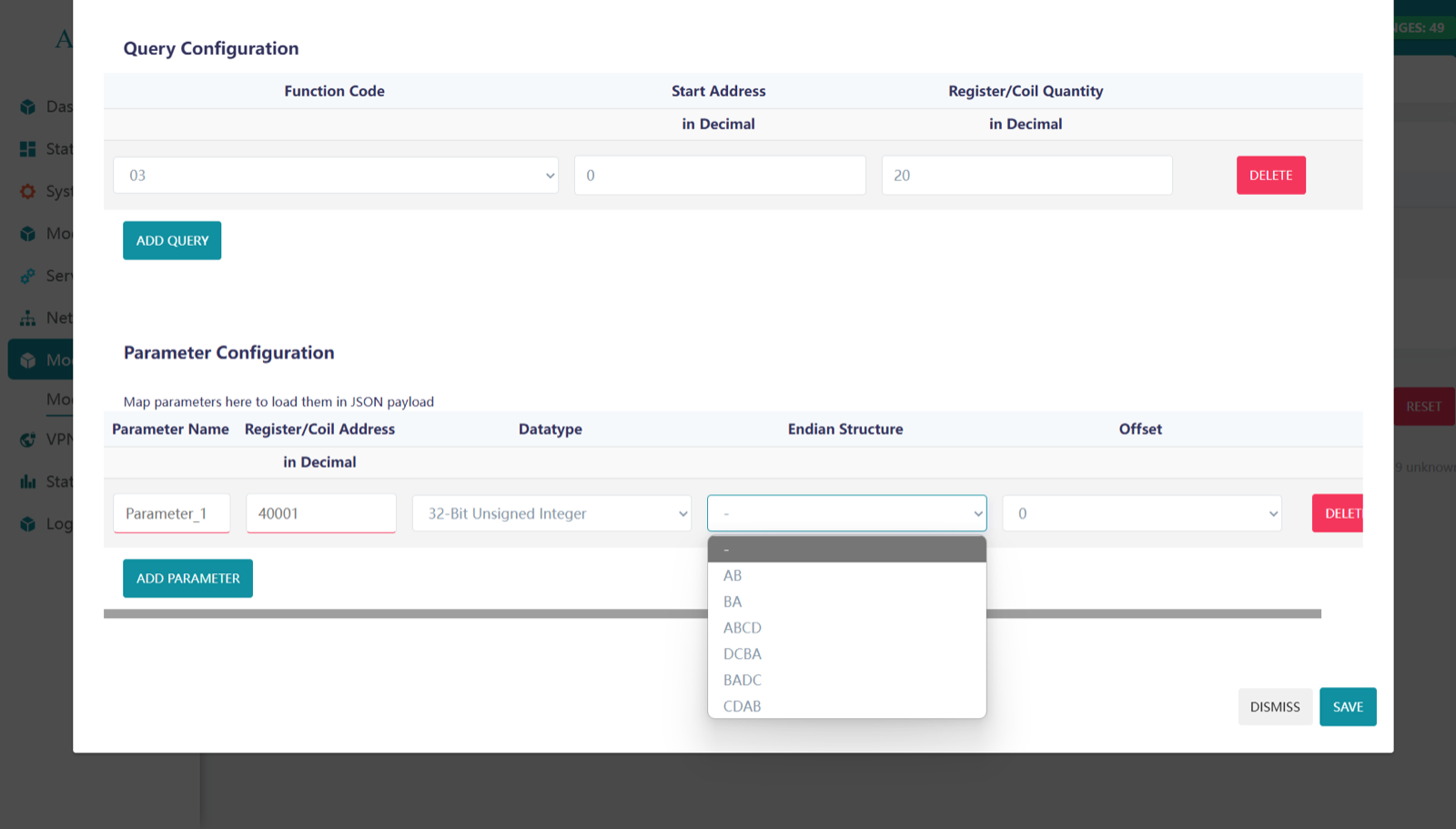
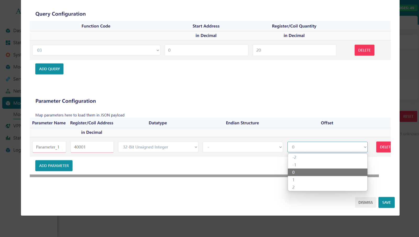
Click on SAVE after entering and selecting the Parameters.
This is how we can configure Modbus and view the details.
And for another slave do the same process by click on ADD SLAVE DEVICE.
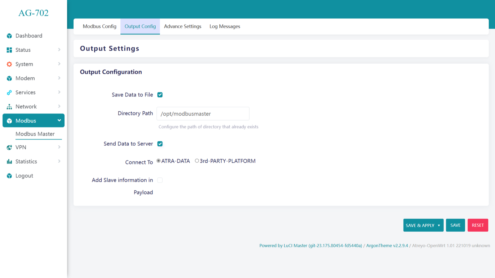
Data output configuration
Click on Output configuration. There are two option:
- Save Data to File.
- Send Data to Server.
We can choose both options and then the data is both sent to the server and saved locally.
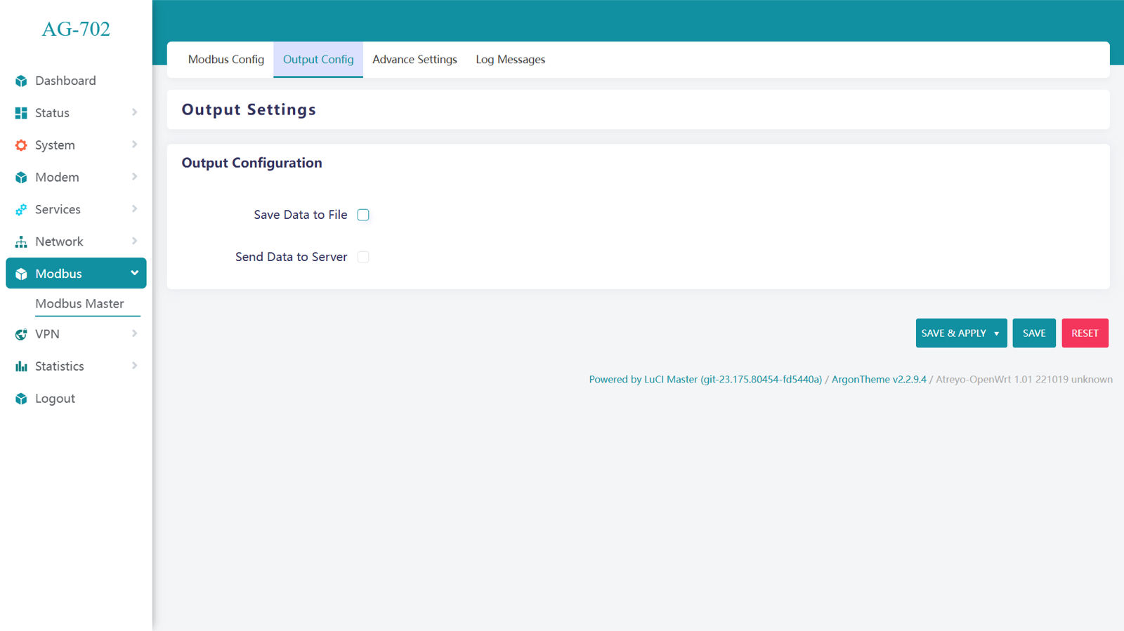
If Save Data to File is selected, it is necessary to specify the folder path.
Send data to server
In Send Data to Server. There are 2 option:
- ATRA-DATA
- 3rd-PARTY-PLATFORM
Atra-Data is Atreyo's system for quick and easy presentation of data in the cloud. In the case of 3rd-PARTY-PLATFORM, we can choose any data platform that communicates using one of the selected ports: HTTP, MQTT or TCP/IP.
ATRA-DATA
ATRA-DATA. In This Data is send direct to the ATRA server without any aditional configuration.
3rd-PARTY-PLATFORM.
There are some parameter required to select protocol – HTTP, MQTT, TCP/IP.
HTTP(s)
Enter the URL For HTTP Post and Header. Where able to Change default header or add new one if needed.
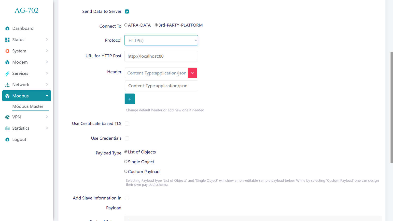
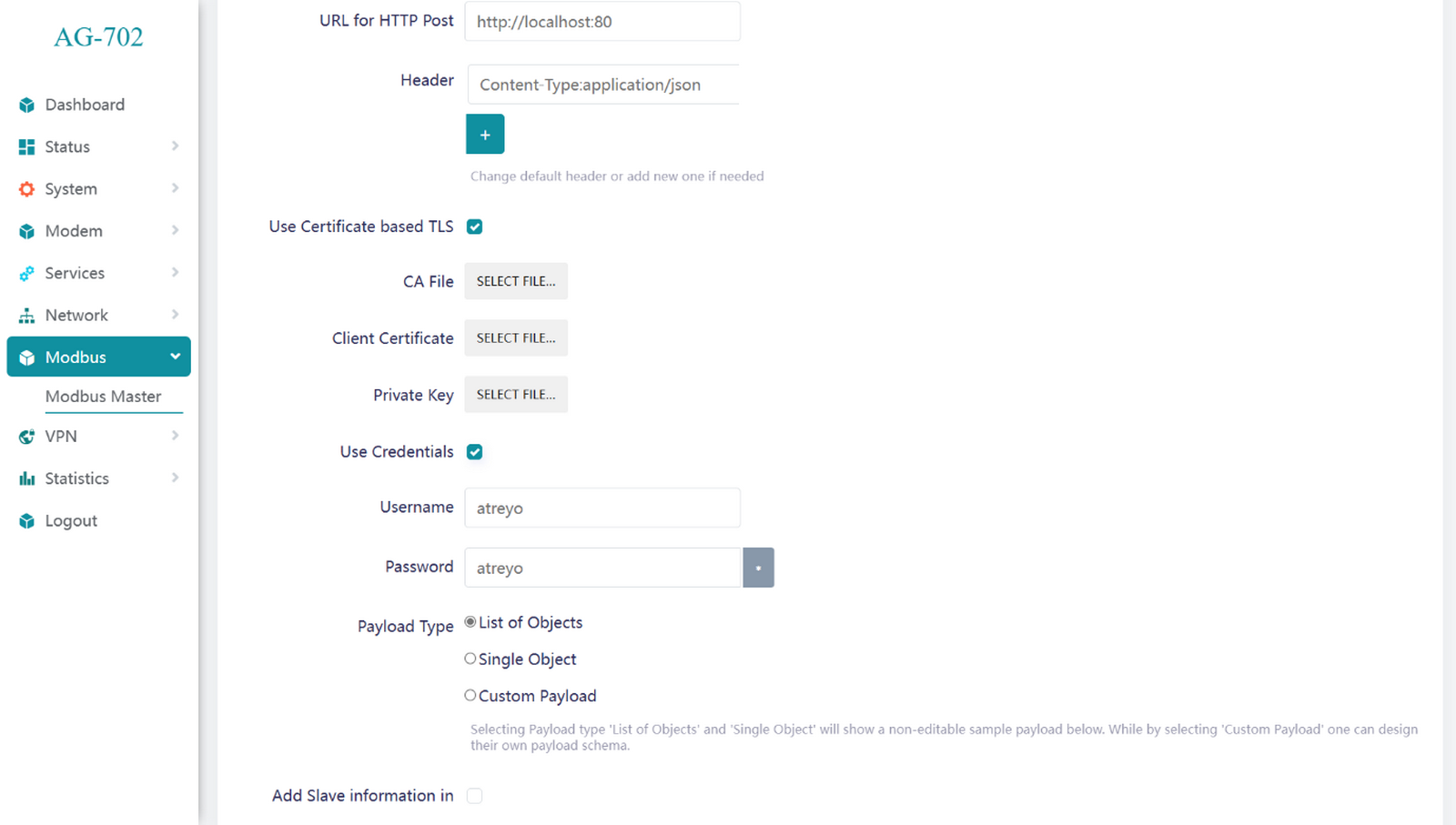
Certificates
To enhance security for data transmission, you can use certificate-based TLS along with credentials.
Certificate-based TLS (Transport Layer Security) require CA(Certificate Authorities) file, Client Certificate and Private key
Credentials often require a username and password for authentication and access control in secure systems.
MQTT
Enter the Server Hostname/IP, Server Port, Publish Topic and Subscribe Topic. Select QoS level as per requirement and Client ID it is Auto-generate.
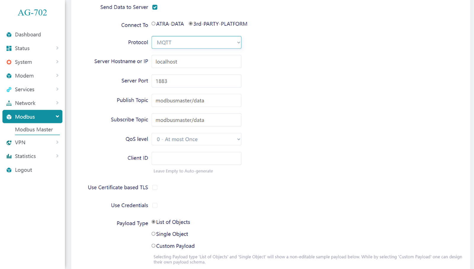
QoS (Quality of Service) level
- QoS 0 (At most once): Fast, no acknowledgment, possible message loss.
- QoS 1 (At least once): Acknowledged, possible duplicates.
- QoS 2 (Exactly once): Highest reliability, no duplicates, uses a four-step handshake.
IoT platform integration
Zoho IoT integration
Integrating the AG-702 gateway with Zoho IoT is very simple. To do this, follow the instructions on the Zoho IoT website link.
Firmware update
The system can be updated via the built-in website. We can update OpenWRT firmware both when the system is running and when it's in U-Boot mode. In cases we need to have a firmware file with a new system compatible with this gateway model. Uploading the incorrect image may cause the device to malfunction.
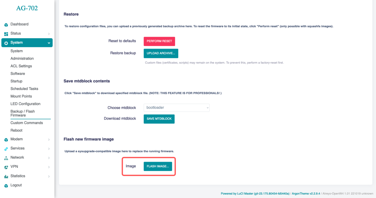
When OpenWRT is running
Go to System > Backup / Flash Firmware. At the bottom of the page is an option to Flash new firmware image. Select the correct system image and click Flash Image.
This is followed by a firmware file selection window.
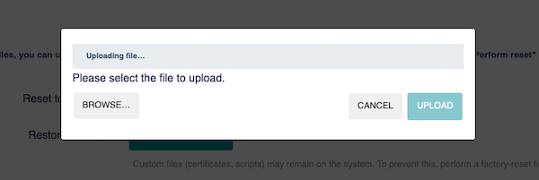
Select the correct file and click upload.
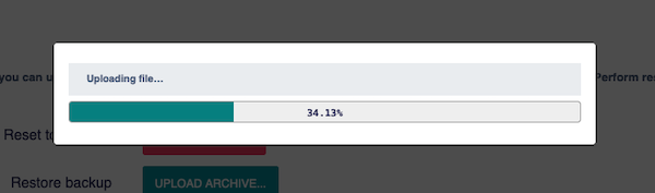
The file will be loaded into the gateway and verified. If it is verified correctly it will go to the window where the option "Keep settings and retain the current configuration" will be checked. If you do not care about keeping the configuration, it is better to uncheck this option.
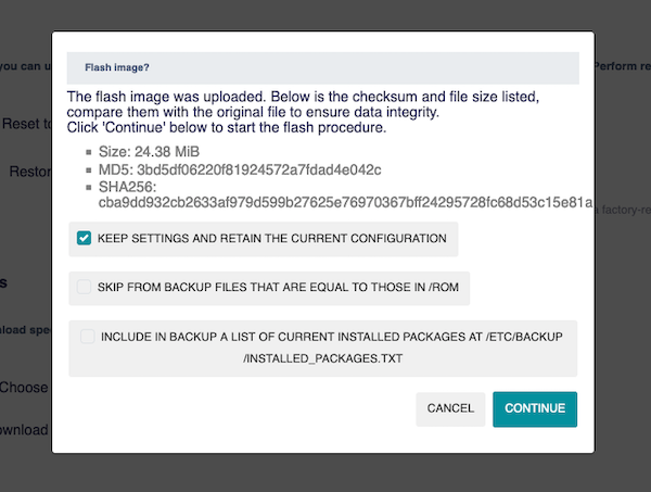
Then you have to wait a few minutes for the system to load and update.
Do not turn off the gateway while the system is being updated. This will damage the system.
By U-Boot mode
This method of uploading firmware should only be used when the system is not working and the firmware cannot be uploaded in the normal way. To enter U-Boot mode press RESET switch for 4 seconds when switching on the power supply. The Gateway should start on U-Boot mode. In U-Boot mode, the white STAT LED glows continuously. To access internal website go to IP 192.168.10.50 and load firmware from proper firmware file provided by Atreyo.
Uploading incompatible firmware not provided by Atreyo will void the warranty.

Then you have to wait a few minutes for the system to load and update.
Do not turn off the gateway while the system is being updated. This will damage the system.
Firmware list
The Gateway works on the OpenWRT operating system. The operating system is specially prepared and compiled for hardware. So when it is booted up, it is ready for use. In addition to the pre-installed application, we provide our own repository of free apps compiled for this Gateway. We update the system regularly to keep the latest version. You can check the latest releases here.
V1.01.05
With built-in Modbus Master. IPV6 support added.
AG-702-LT-EU version
| Firmware Version | File name | Kernel |
OpenWRT |
Date |
| V1.01.05a | download |
5.15.71 | 08.01.2025 |
AG-702-LT-GL version
| Firmware Version | File download |
Kernet |
OpenWRT |
Date |
| V1.01.05a | download | 5.15.71 | 08.01.2025 |
V1.01.05a
Add pendrive support (kmod-usb-storage)
AG-702-LT-EU version
| Firmware Version | File name | Date |
| V1.01.05a | atreyo-openwrt-AG-702-V1.01.05a-EC200 | 11.03.2025 |
AG-702-LT-GL version
| Firmware Version | File name | Date |
| V1.01.05a | atreyo-openwrt-AG-702-V1.01.05a-EG25 | 11.03.2025 |
V1.01.07
Add QMI communication with LTE modem.
AG-702-LT-EU version
| Firmware Version | File name | Date |
| V1.01.07 | atreyo-openwrt-AG-702-V1.01.07-EC200 | 05.04.2025 |
AG-702-LT-GL version
| Firmware Version | File name | Date |
| V1.01.07 | atreyo-openwrt-AG-702-V1.01.07-EG25 | 05.04.2025 |
V1.01.09
Changes:
- Added USB mapping/rename script
- Modbus master: version 5.3.3
- SIM switching: version 2.2.3
- WiFi power correction
AG-702-LT-EU version
| Firmware Version | File name | Date |
| V1.01.09 | atreyo-openwrt-AG-702-V1.01.09-EC200 | 23.08.2025 |
Safety information
Operating environment
- The device is designed to be installed in clean, dust-free and insect-free places
- Operating temperature: -25 ~ 65°C (-13 ~ 149°F).
- Humidity range is 10% to 95% (non-condensing). Use the device in a dry environment.
- Away from heat sources and direct sunlight.
- It must not be exposed to acid fumes, salts and other chemicals.
- The device must not be used in places where there is a risk of gas explosion.
Use in inappropriate conditions may damage the device or shorten its life.
Electrical and power supply safety
- The device is powered with a voltage in the range of 8-48V. Voltage up to 24V is considered safe. Be especially careful when supplying them with higher voltages.
- The device has the ability to control the output with the mains voltage of 160V. In this case, it is especially necessary to observe the safety rules during installation.
- Use only approved accessories
- Use the supplied power adapter or a good quality certified power adapter with the correct supply voltage range and sufficient power.
- Only use approved accessories like antenna etc.
Only a person with qualification and appropriate knowledge should install the device.
Malfunctioning and damaged device
- Do not disassemble the device.
- Only qualified personnel must service or repair the device or its accessories.
- If water or other liquid has got into the device, or if it looks mechanically damaged, do not connect the device, but take it to an authorized service center.
Radio frequency exposure
This device has been designed and manufactured not to exceed radio frequency energy emission limits set by regulatory agencies. To comply with RF exposure guidelines, the device must be used at least 20 cm away from a person's body. Failure to follow these instructions may result in exceeding the applicable RF exposure limits. This only applies to models with a built-in LTE modem.
What to do and what not to do
- You are solely responsible for the use of the device and any consequences of its use.
- Do not store or use the device in harsh environments such as dust, gases, oils, chemical vapors and damp places.
- Do not throw the device and its accessories. Handle with care.
- The device heats up during operation. Ensure proper ventilation.
- If you need to dispose of your device, check your local regulations for recycling and disposal of electronics.
- Route power, Ethernet, and antenna cables properly so that they cannot be accidentally pulled out.
- The device should be used and kept away from small children.