AG-801
The AG-801 Gateway can be controlled via TCP commands from server. All Modbus queries can be controlled from server. In addition Gateway has support of JSON string format but limited to Modbus interface. JSON communication is one way communication dedicated mostly to energy meters and sensors. In case of failure of GSM communication, Gateway has capability to store records in internal memory and sending archive data to the server after communication is reestablished for continuous energy monitoring. This option is available only in JSON string format. It is not supported by TCP/IP communication. TCP/IP communication can control all modbus features, send commands and control any device like PLC in real time.
Please read carefully before starting. Also read the product safety information.
General Information
| Download technical specification | Technical Specification |
The AG-831 is a Gateway dedicated to work witch central controlling and monitoring systems. It support two-way communication with server trough LTE/GSM or Ethernet. It has inbuilt timer with 10 ON/OFF schedule within 24h, auto configurable sunrise/sunset timer based on geolocation and has 3 independent relays. Every output can be controlled by separate time schedule. Gateway has isolated Modbus RTU interface to communicate with energy meters, PLCs and other Modbus devices. Can be configured by: internal website, SMS, string from server and configuration file loaded in predefine URL. For accurate time and location it has GPS and RTC. This is updated version of AG-811.
- LTE and GSM connectivity
- GNSS for accurate time and location
- 3 independent NO outputs
- Opto-isolated Modbus RTU
- 2 opto-isolated digital inputs
- SMS alert and with mobile number filtering
- Timer with astronomical timer
- Internal website for configuration
- LAN with PoE
- Output status control by string from server and by SMS
- Modbus archive data in internal memory
- Aluminium compact size casing
- 35mm DIN rail mounting
Control and configuration option list
Gateway can be controlled through:
- Commands from TCP/IP server
- SMS
- Configuration of Gateway can be done through:
- Internal website
- Configuration file from URL
- Commands from TCP/IP server
- Configuration file from predefined URL
Hardware informations
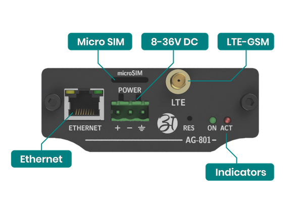
Top view

Side view
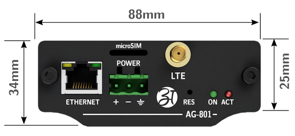
Connectors
The AG-831 has an RJ45 on the top with LED indicators and two SMA female sockets. There is also a two pluggable sockets on the bottom of the gateway.
Power supply
The device is powered by external DC power supply. Minimum supply voltage is 8V and maximum 36V. Preferred 24V. Select the power supply requirement according to the below table. The device had protection against high voltage and reverse polarity. High voltage will blow inbuilt fuse. Reverse voltage will not damage device – the device will simply not work on reverse voltage.
| Supply Voltage | Minimum A requirement | Suggested power supply rating |
| 12V | 1A |
1.5A |
| 15V |
1A |
1.5A |
| 24V |
0.5A |
0.7A |
| 32V |
0.5A |
0.5A |
PoE
The Gateway can also be powered via PoE in the range of 8-36V using unused pairs of wires in the LAN cable. Below is the pinout of the RJ45 socket.
| Pin number |
Function |
Comment |
| 1 |
RX+ | Data |
| 2 |
RX- | Data |
| 3 |
TX+ | Data |
| 4 |
DC+ | Power supply positive |
| 5 |
DC+ | Power supply positive |
| 6 |
TX- | Data |
| 7 |
DC- | Power supply negative |
| 8 |
DC- | Power supply negative |
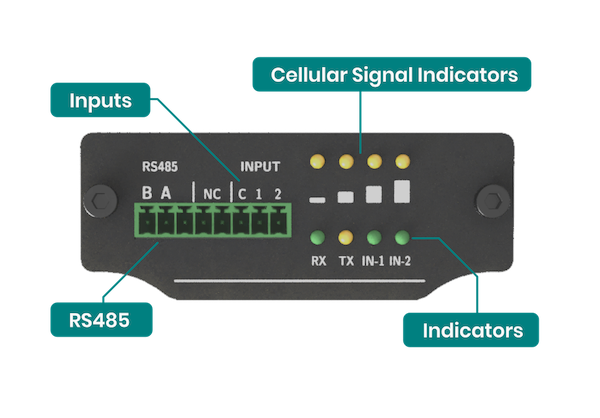
LED indicators
The device has 2 LED indicators on the antenna side and 8 on the connector side. On antenna side are power (green) and activity (yellow) indicator. The behaviour of activity LED is according to the table.
| LED | Function | Behaviour |
|---|---|---|
| POWER | Normal working condition | permanent ON |
| ACT | Normal working condition | blinking every 1 second |
| LTE | LTE/GSM connection | blinking if LTE/GSM active |
| LTE | LTE/GSM signal strength | 0-25%, 25-50%, 50-75%, 75-100% |
| Serial | RX and TX data indication of RS485 | blinking on data transfer |
| Inputs | Input 1 and 2 high level indication | ON if input high |
Configuration manual
Connect the correct power supply. You can choose the right power supply in the power supply section.
Then connect the LAN cable to the gateway to the router. It is important that the IP address is in the range of 192.168.10.xxx.
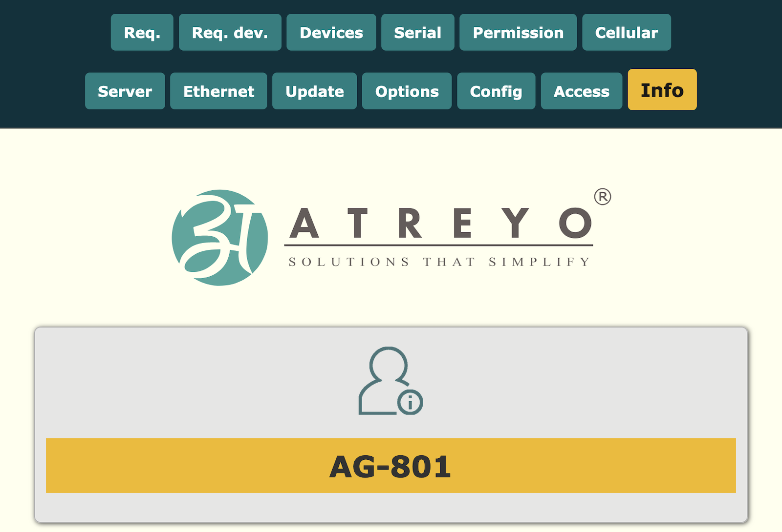
To enter internal website of Gateway make proper LAN connection and in browser address tab enter Gateway IP. The default IP is:
192.168.10.50.
User name: atreyo
password: atreyo.
- A, B, C – for digital outputs
- Req – request modbus device
- Req. dev. – request modbus device
- Devices – RTU configurations devices
- Serial – configuration serial communication
- Permission – permission configuration for mobile numbers
- Guard – for monitoring communication and activity
- GSM – GSM, LTE, GPRS configuration like APN, password etc.
- Server – server configuration
- Ethernet – Ethernet configuration
- Update – upload firmware and remote update configuration
- Options – for date, time, location, default etc.
- Config – backup, restore and remote configuration.
- Access – access configurations for internal website
- Info – main page with information about model, firmware version etc.
Ethernet
The LAN interface use standard RJ45 8 pin connector with LED indicators. The connector support PoE class A, with power supply range 8-36V DC. If we use screw terminal power connector to power the device the LAN line is protected against back voltage from device. The device is protected from reverse power polarity. If unknowingly it is reverse connected, the Gateway will not work, but will not be damaged. Follow the diagram of connection.
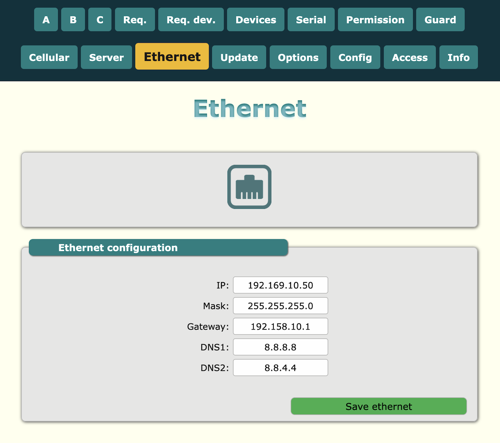
Configuration of Ethernet
Ethernet configuration for LAN. Default value is:
IP = 192.168.10.50
Mask = 255.255.255.0
Gateway = 192.168.10.1
DNS1 = 8.8.8.8
DNS2 = 8.8.4.4
LTE modem
Gateway has inbuilt LTE modem with support of LTE and GPRS.
SIM card
The device support microSIM with voltage 1.8 and 3V. The card holder is push-in/push-out type. Ensure inserting SIM card in proper direction according to the illustration.
Antenna
The device has two female SMA connector for LTE/GSM antenna and for GPS antenna. For proper working it is necessary to connect LTE + GSM band antenna and proper GPS antenna. Antenna line is 50Ω type. Do not switch on device without antenna connected. For better connectivity in remote area it is necessary to use high gain antenna and place it outside of electrical panel box.
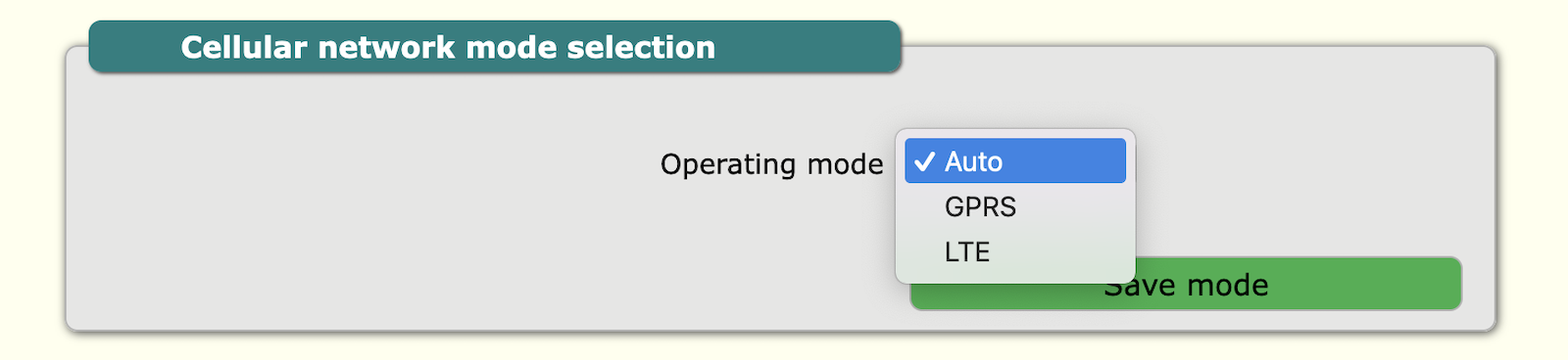
Cellular network configuration
Configuration for mode of connection. Default is auto. But if you are using a SIM card that has only GPRS available, set the connection type to GPRS. If it has only LTE then select LTE and if it has both then you can leave it at auto.
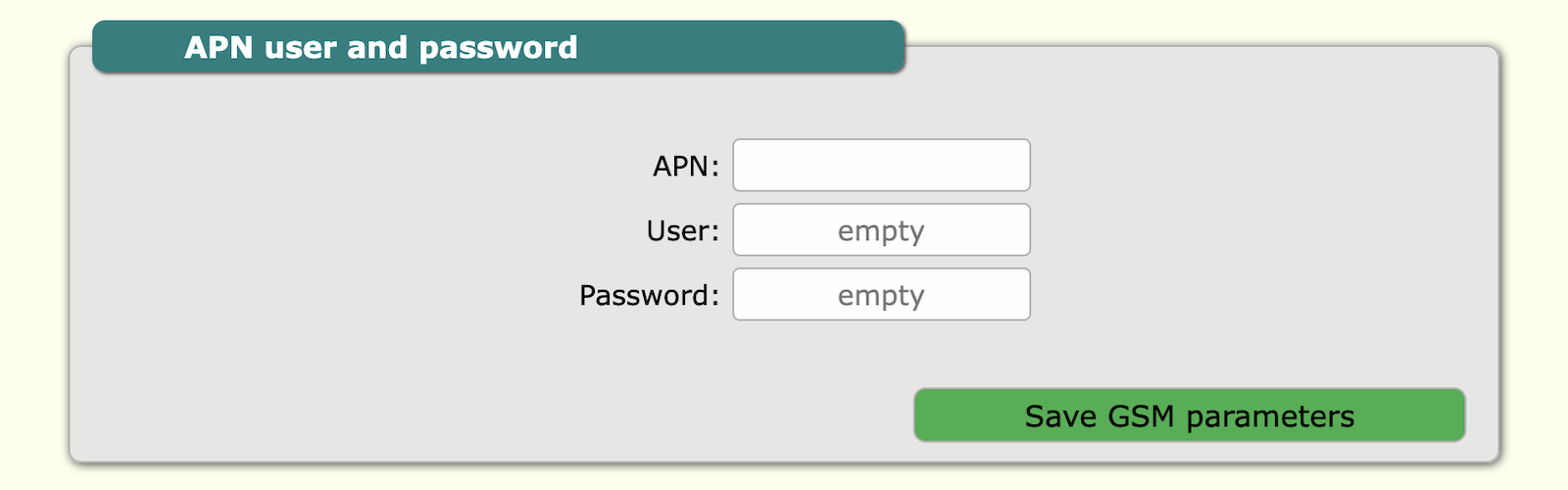
 GSM configuration include: APN, user and password.
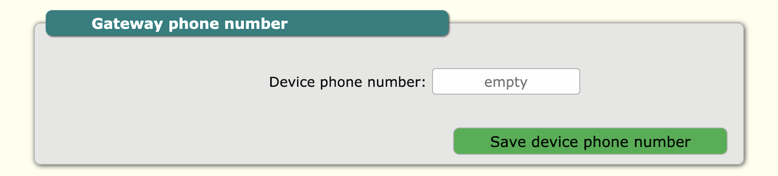
Gateway phone number is Gateway SIM card phone number. It is not necessary to provide this, but in future this information is accessible by TCP/IP and for maintenance is good practice to add this number.
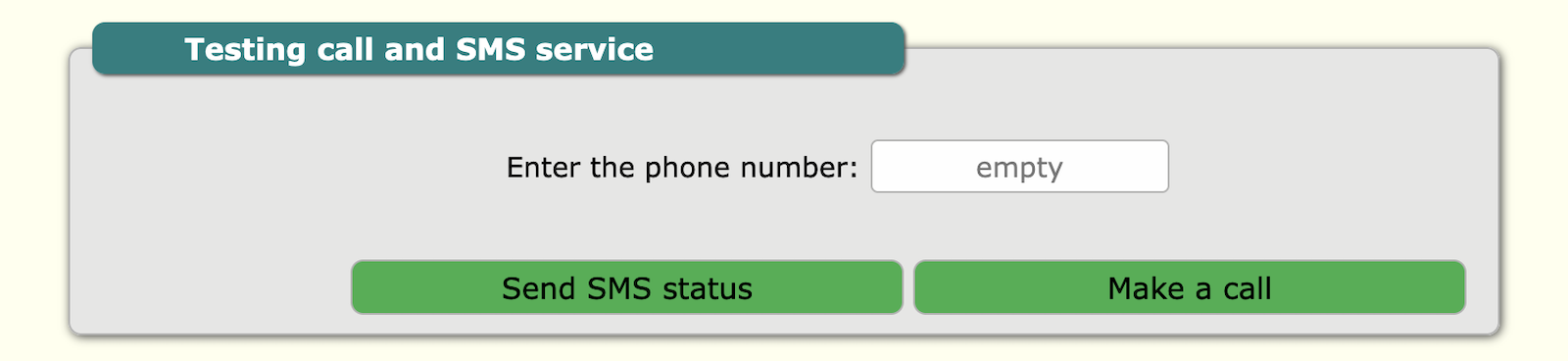
Cellular network testing is for testing of SIM card and network. You can add your number and Gateway will call or send SMS to this number. For this purpose, call and SMS support must be enabled with the mobile operator.
GNSS
The gateway has a built-in GNSS module which is used as a source of accurate time and location. GNSS settings are known in the LTE modem settings tab
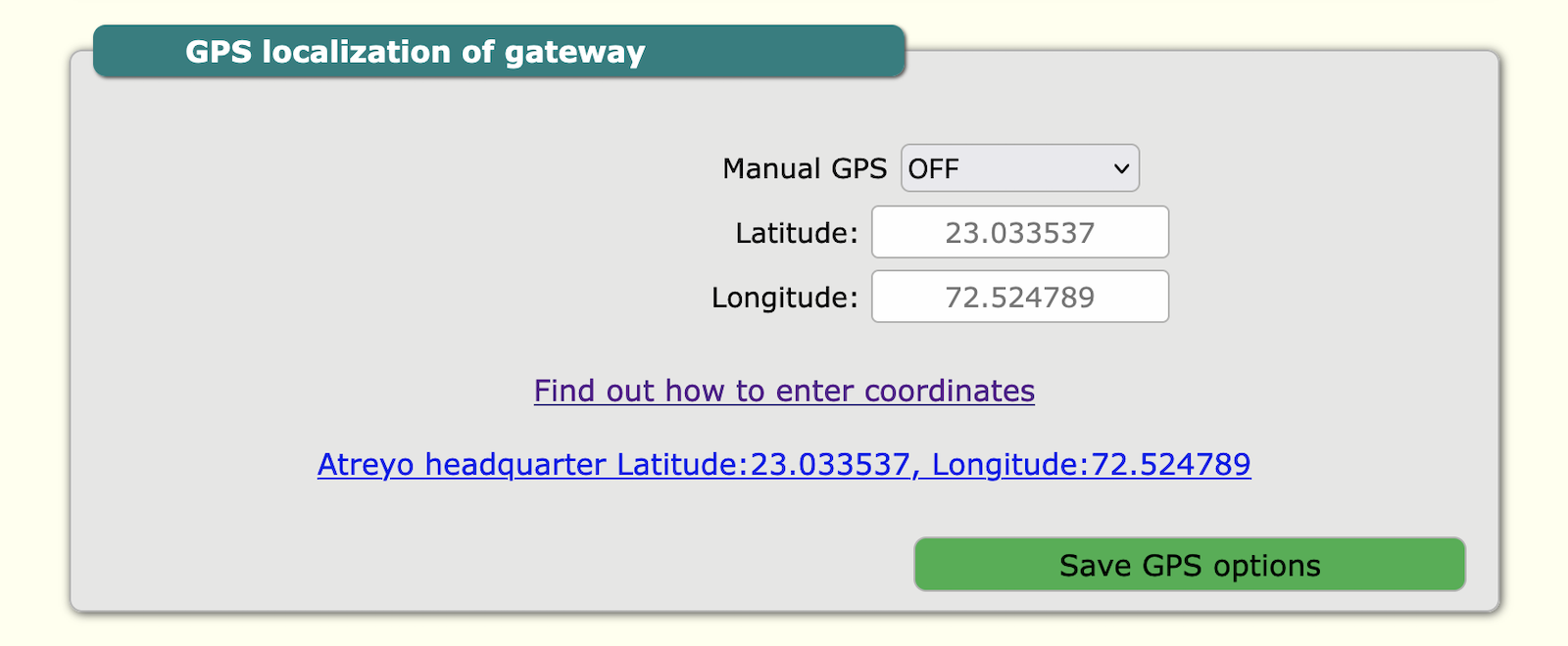
Manual GPS
The location is needed for the solar timer system. In some situations, the gateway is placed in such a location that it does not catch the GNSS signal, and for this purpose there is a manual GPS option. To use this option, you need to enter the longitude and latitude manually.
Powering the active GNSS antenna
The gateway has the ability to accommodate both passive and active GNSS antennas. The supply voltage of the active antenna is 3.3V. To enable the power supply, select Antenna power supply ON.
RS485 – Modbus
The device has opto-isolated RS485 interface with support of Modbus RTU. It is dedicated to energy meter, voltage meter and any Modbus device like PLC which support Modbus RTU protocol. The device supports multiple Modbus devices with separate address range. It is possible to directly send and receive any value of register from server. Please follow proper connection of A and B signals from device to A and B signals in power meter. If the polarity is reversed there will be no data transmission. All modbus configuration like baud-rate, parity, address available in internal website.
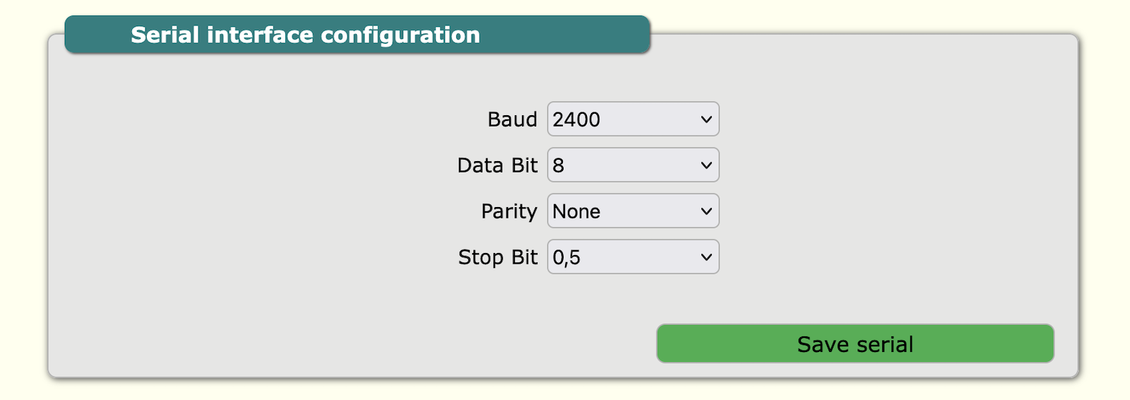
Serial Configuration
In this section are RS485 parameter configuration: baud rate, data bit, parity and stop bit.
| Parameter |
Option/range |
| Baud-rate | 2400 to 460800 |
| Data bit | 8, 9 |
| Parity | None, Even, Odd |
| Stop bit | 1, 1.5, 2 |
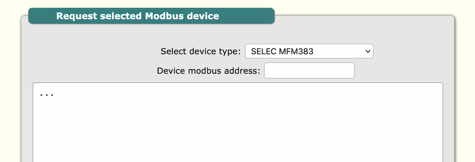
Req. dev. – Request device log
In this section is visible log of modbus devices. In this tab is optional feature to make support for Selec® company meter without necessity to set modbus device details. In window the reply from Selec® device will be visible. Now 2 models of meters are supported MFM383 and EM2M.
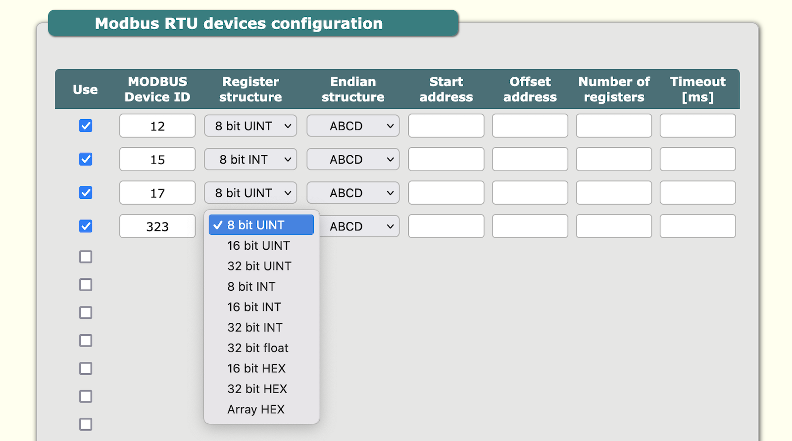
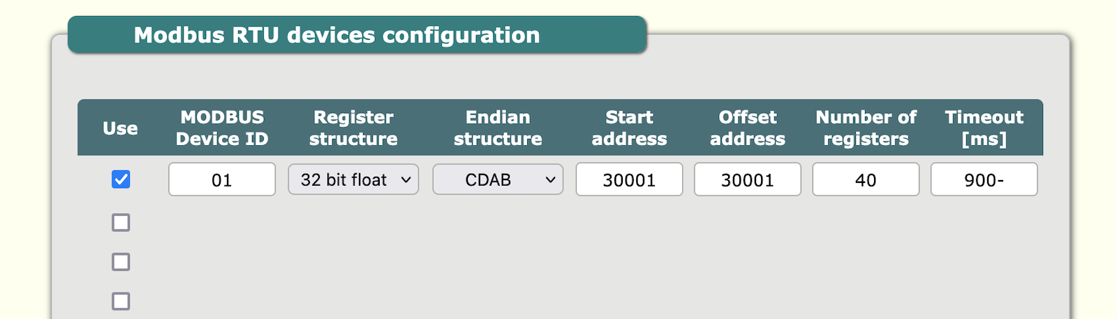
Devices – Modbus devices
Modbus devices configuration of modbus devices connected to Gateway. Configuration of: device ID, register, endian, start address, offset address, registers, timeout. It can add multiple devices up to maximum 16.
| Sn | Parameter | Details information |
|---|---|---|
| 1 | Use | To activate device configuration |
| 2 | Modbus Device ID | The ID of modbus device. 01 up to FF |
| 3 | Register structure | 8 bit UINT, 16 bit UINT, 32 bit UINT, 8 bit INT, 16 bit INT, 32 bit INT, 32 bit float, 16 bit HEX, 32 bit HEX, Array HEX |
| 4 | Endian Structure | ABCD, BADC, CDAB, DCBA |
| 5 | Start address | First Modbus register address |
| 6 | Offset address | Offset address for add or subtract of actual query address, according to slave device data storage system |
| 7 | Number of registers | How many registers needed to query |
| 8 | Timeout [ms] | Response time-out for query |
Example
Example for query: 01 04 00 00 00 28 F0 14
In this example F0 14 is checksum CRC-16 big endian.
Digital inputs
The device has 2 opto-isolated up to 2500Vrms digital inputs with seperate minus signal. The signal maximum voltage is 30V DC. Inputs support only DC signal with proper polarisation. The input digital high is from 3.5V to Vmax, and digital low from 0 to 2V. Inputs can be controlled also by open collector circuit with common positive. The input resistance is approx 2.7k. The input terminal diagram is as per below.

1+/2+ = digital input positive
1-/2- = digital input negative
If by mistake reverse polarity signal is connected to input the input will not work, but will not be damaged.
Digital input status
The status of the inputs can be checked in the tab info>state of input.

Users - passwords
Password configuration
This section is for internal website access. Default password is atreyo.

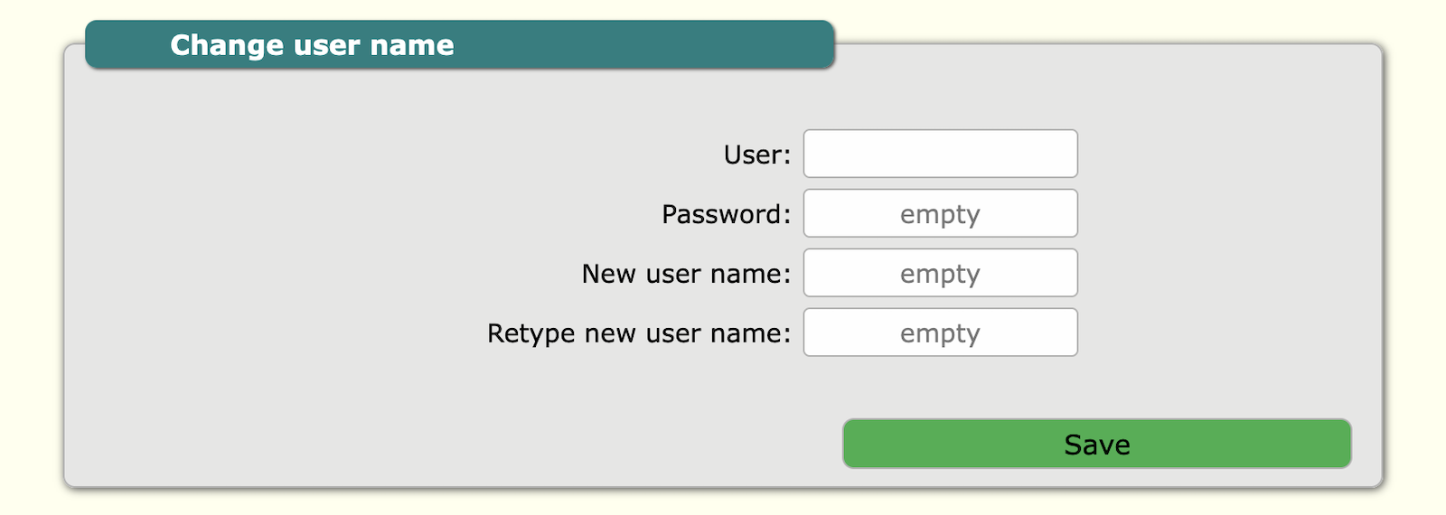
User configuration
For user change. Default user is atreyo.
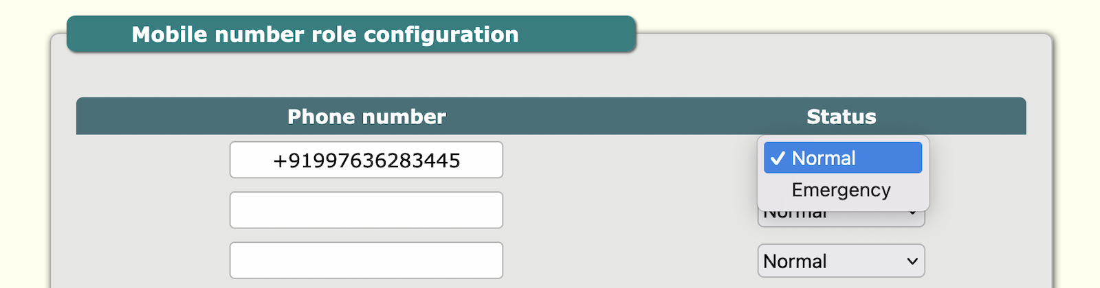
Permissions and role
This tab is for permissions of mobile numbers to protect from unauthorised access via SMS commands. By default any number can access Gateway but after input of any number only number from list is able to control Gateway. Mobile number has roles of "normal" and "emergency". Normal role allow to make control of Gateway, and emergency in addition is the emergency number for alerts. In AG-831 digital inputs high status is event for emergency SMS. It is possible to add maximum 13 telephone numbers. Number format with + before country prefix.
System
Multi-function reset button
The AG-811 has multifunction reset button. This button is used to:
- reset device
- restart device
- make default configuration
Multi-function reset button
The AG-811 has multifunction reset button. This button is used to:
- reset device
- restart device
- make default configuration
| Press and hold the reset button | Behaviour | Remark |
|---|---|---|
| 1 to 10 seconds | power off | If device is using battery backup |
| 10 to 20 seconds | restart device | |
| 20 to 30 seconds | make default | |
| 30 and more than 30 | exit |
Firmware update
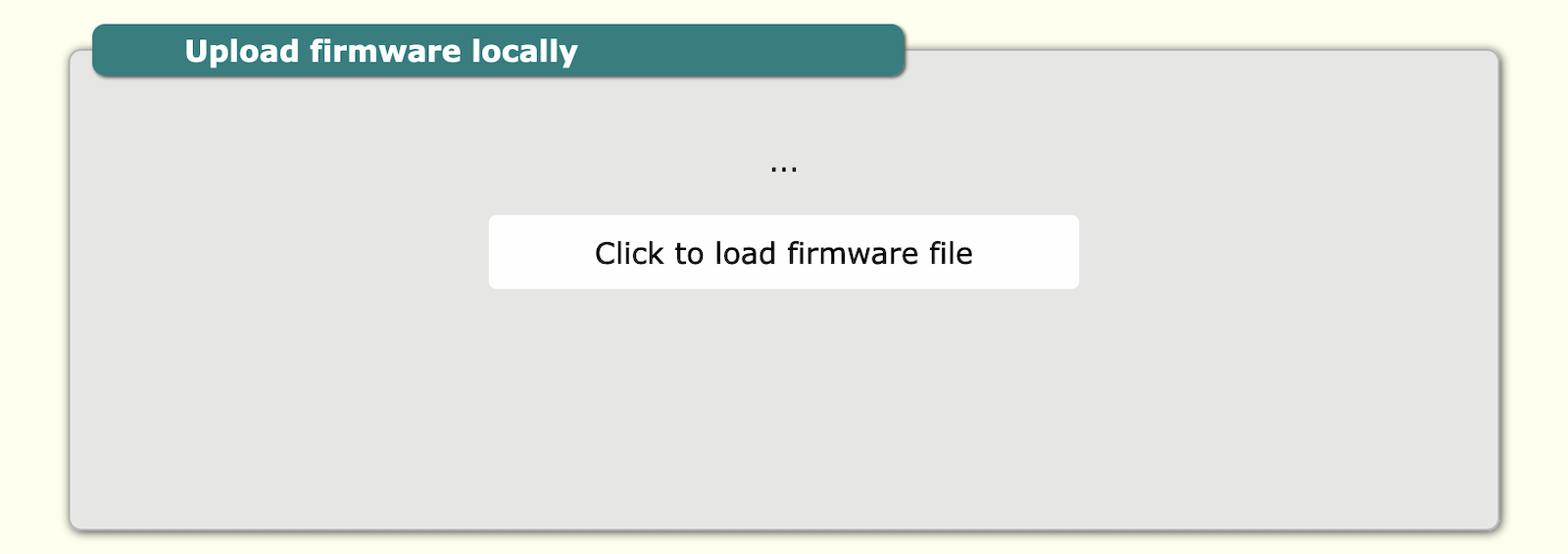
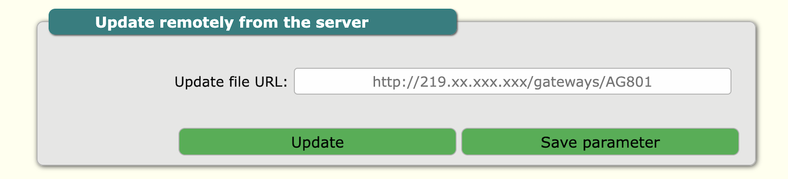
The Gateway can update firmware from remote URL and locally direct by uploading BIN file with proper firmware. To load firmware click load firmware file and select firmware. After loading Gateway will automaticity restart. Firmware update in normal condition will not reset configuration.
Local update
Update from server
Backup / restore config
The gateway allows you to backup your configuration and also upload the configuration to the gateway. To do this, you need to enter the config section.
Local backup/restore

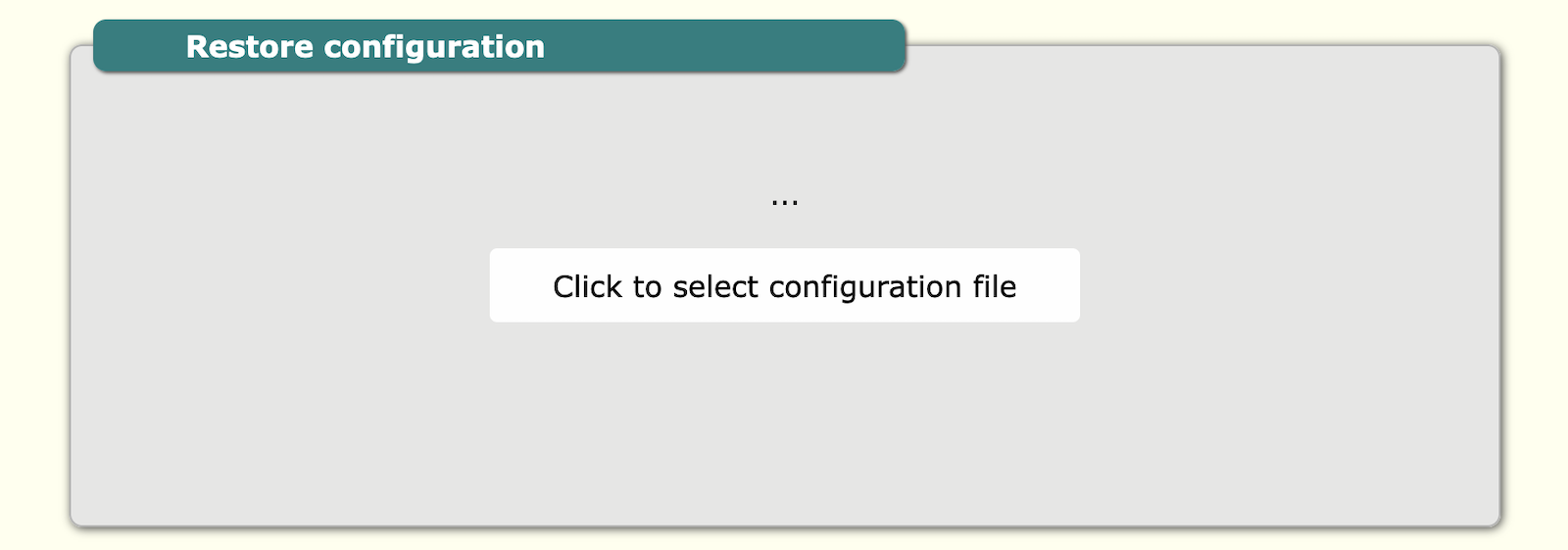
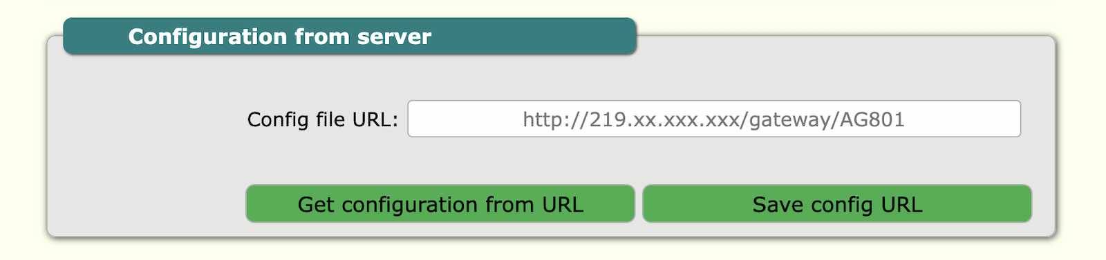
Configuration from server
Also, it is possible to download the configuration from the server. To do this, enter the correct address of the server and the configuration file.
SMS functions
Safety information
Operating environment
- The device is designed to be installed in clean, dust-free and insect-free places
- Operating temperature: -25 ~ 65°C (-13 ~ 149°F).
- Humidity range is 10% to 95% (non-condensing). Use the device in a dry environment.
- Away from heat sources and direct sunlight.
- It must not be exposed to acid fumes, salts and other chemicals.
- The device must not be used in places where there is a risk of gas explosion.
Use in inappropriate conditions may damage the device or shorten its life.
Electrical and power supply safety
- The device is powered with a voltage in the range of 8-36V. Voltage up to 24V is considered safe. Be especially careful when supplying them with higher voltages.
- Use only approved accessories
- Use the supplied power adapter or a good quality certified power adapter with the correct supply voltage range and sufficient power.
- Only use approved accessories like antenna etc.
Only a person with qualification and appropriate knowledge should install the device.
Malfunctioning and damaged device
- Do not disassemble the device.
- Only qualified personnel must service or repair the device or its accessories.
- If water or other liquid has got into the device, or if it looks mechanically damaged, do not connect the device, but take it to an authorized service center.
Radio frequency exposure
This device has been designed and manufactured not to exceed radio frequency energy emission limits set by regulatory agencies. To comply with RF exposure guidelines, the device must be used at least 20 cm away from a person's body. Failure to follow these instructions may result in exceeding the applicable RF exposure limits. This only applies to models with a built-in LTE modem.
What to do and what not to do
- You are solely responsible for the use of the device and any consequences of its use.
- Do not store or use the device in harsh environments such as dust, gases, oils, chemical vapors and damp places.
- Do not throw the device and its accessories. Handle with care.
- The device heats up during operation. Ensure proper ventilation.
- If you need to dispose of your device, check your local regulations for recycling and disposal of electronics.
- Route power, Ethernet, and antenna cables properly so that they cannot be accidentally pulled out.
- The device should be used and kept away from small children.