ALWG-1638
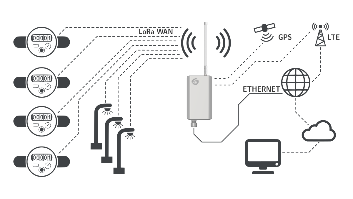
Atreyo LoRaWAN® gateway is powered with an ARM Cortex-A7 processor with ease of outdoor installation and IP67-rated environment-resistant aluminum enclosure to support your smart city, smart industry, professional LoraWAN® network applications, and industrial control systems.
It also has an emergency Supercap backup supply for the last message.
The gateway’s dual SIMs ensure network connectivity redundancy.
ALWG-1638 has inbuild:
- ChirpStack MQTT forwardeR
- ChirpStack Network Server
- ChirpStack Application Server
- Node-RED
Please read the user manual carefully before starting and proceeding with the device.
Also, read the product safety information.
- General Information
- Configuration Manual
- Chirpstack LNS
- Node-RED
- Use cases/ Examples
- Firmware releases
- Safety information
General Information
| Download technical specification | Technical Specification |
Model selection
Different LoRaWAN Gateway models are available depending on frequency band/region and on the periphery availability and it's type.
| Model |
Lora frequency / Country | Cellular | ||||
| IN |
US |
EU |
IN |
EU |
GL |
|
| ALWG-1638-IN-LT-IN | √ | √ | ||||
| ALWG-1638-IN-LT-EU | √ | √ | ||||
| ALWG-1638-IN-LT-GL | √ | √ | ||||
- ALWG-1638-IN-LT-IN comes with IN865 region and 4G LTE modem certified for India region.
- ALWG-1638-IN-LT-EU comes with IN865 region and 4G LTE modem certified for Europe region.
- ALWG-1638-IN-LT-GL comes with IN865 region and 4G LTE modem certified all over the world.
Models with other configurations are available by special order. See “Technical Specification” for how to select the correct model.
Hardware information
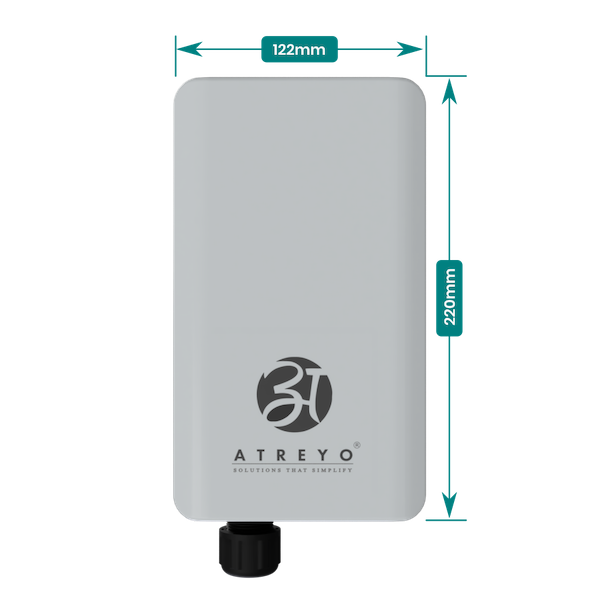
The Gateway is made from aluminium back and UV resistant PC front. It is IP67.
Front view dimensions
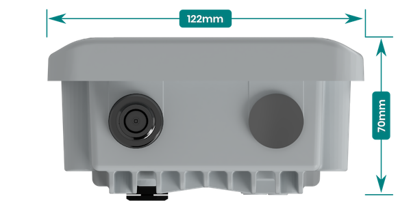
Top/Bottom view dimensions
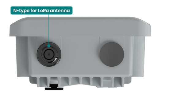
Top connectors
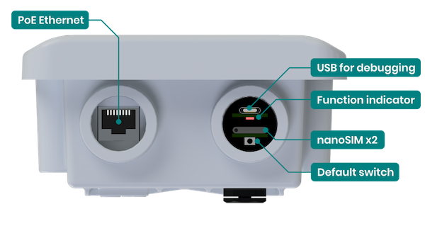
Bottom connectors
Power Supply
Connect the gateway to the power supply as referenced in the below diagram, and use the standard input/output-rated power adapter as per safety guidance.
The Gateway is to be powered via isolated PoE in the range of 37-57V DC.

The above connection diagram shows two ways to connect the gateway to the network and power supply.
PoE Ethernet pinout
Below is the PoE Ethernet pinout for reference.
| PIN number | Function | Remark |
| 1 |
RX+ | Data |
| 2 |
RX- | Data |
| 3 |
TX+ | Data |
| 4 |
DC+ | Power supply positive |
| 5 |
DC+ | Power supply positive |
| 6 |
TX- | Data |
| 7 |
DC- | Power supply negative |
| 8 |
DC- | Power supply negative |
Block diagram
A block diagram of the device is shown below.
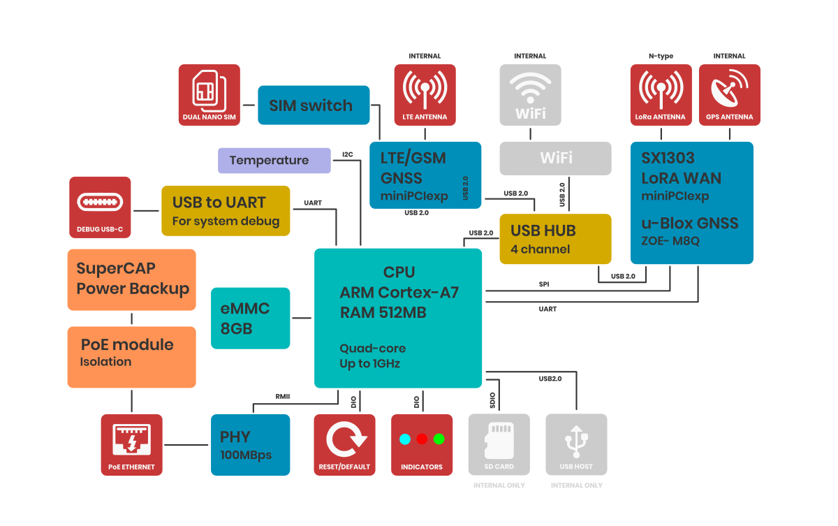
Note: USB host and microSD card are not available to the user. They are only for the purpose of developing your own software and updates. In case the user would like to use them, Atreyo's permission is required, otherwise the warranty will be void.
Configuration Manual
First start
After unpacking, the gateway is in ready-to-use condition but requires a few configurations to adapt to the required functions.
Power Supply
Connect the gateway to the power supply as referenced in the below diagram, and use the standard input/output-rated power adapter as per safety guidance.
The Gateway is to be powered via isolated PoE in the range of 37-57V DC.
The above connection diagram shows two ways to connect the gateway to the network and power supply.
Connect to the network
DHCP
If the gateway is by default in DHCP mode proceed with method 1, which is to connect the gateway directly to your desired WAN network.
- Once connected as per the standard method you can find out the gateway IP of the gateway by using any IP scanner tool or using a command prompt by the "arp -a" command, to identify the gateway take reference to the Ethernet MAC ID.
- After getting the correct IP open any browser and enter the host IP there to access the web UI of the gateway.
Static IP
If the gateway is by default set to static IP, go for method 2 … (Default)
- Connect the LAN cable to the laptop instead of the router and configure your Ethernet IPv4 settings as below, i.e 192.168.10.60
- After configuration open the browser and open the web UI using 192.168.10.60
| IP assigment |
Manual |
| IPv4 address: |
192.168.10.100 |
| IPv4 subnet prefix lenght |
24 |
| IPv4 gateway |
192.168.10.60 |
Now, Go to Network > interfaces and switch IP protocol to "br-lan" to your desired settings.
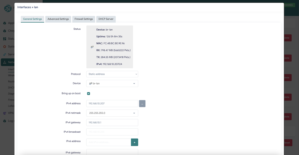
You can configure gateway either in DHCP client mode orelse go for Static IP (as shown above), Feed your desired IP in static mode.
Once web UI access method is smoothly configured proceed to explore web UI configuration options after rebooting the gateway once.
Open the LuCI web interface
Through Ethernet
To access the LuCI WebUI, connect the gateway by your convenient method to the local network and enter the assigned IP address in any web browser. Please note that it may take some time from powering on the gateway to booting up the system. When the green LED in the bottom right side socket starts flashing, after about 10-15 seconds the built-in website becomes available to access.
Enter the host IP address and you will find the URL look a like as shown in the below image.
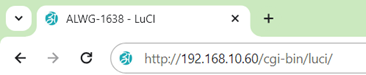
Below image shows the login page of Gateway webUI.

Default credentials are user/pass: root/root
Through the WiFi interface (if WiFi available)
By default, the gateway creates its hotspot, which is called "ALWG-1638". The network is unsecured. Connect to this network find out the host IP by the same method and enter the IP in the address bar of your browser.
WiFi credentials : ALWG-1638/atreyo12
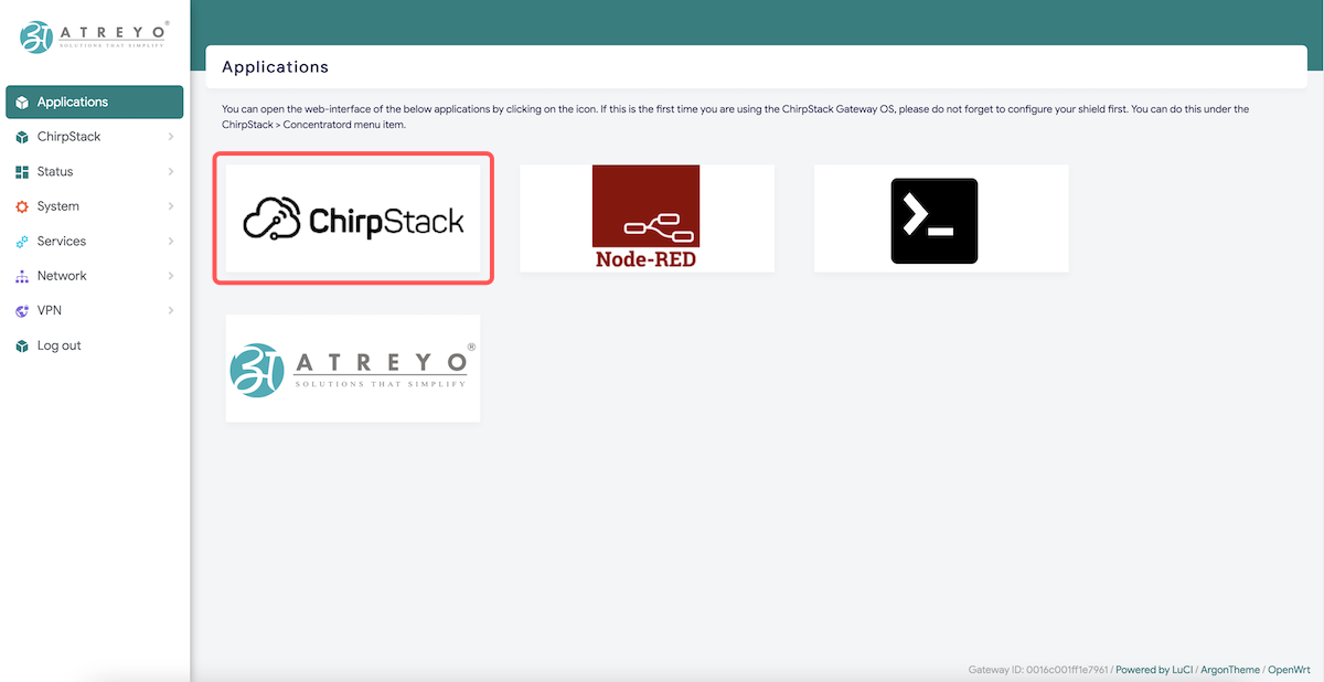
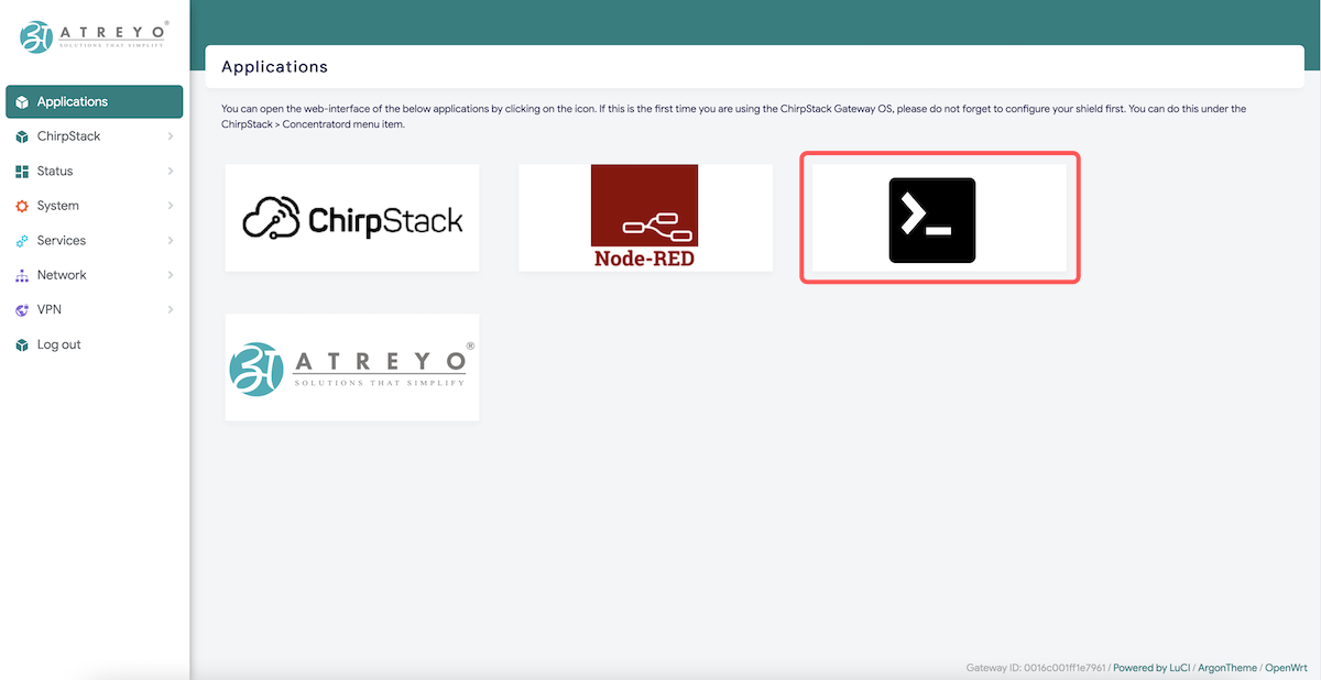
After logging in, you are automatically taken to the Application page:
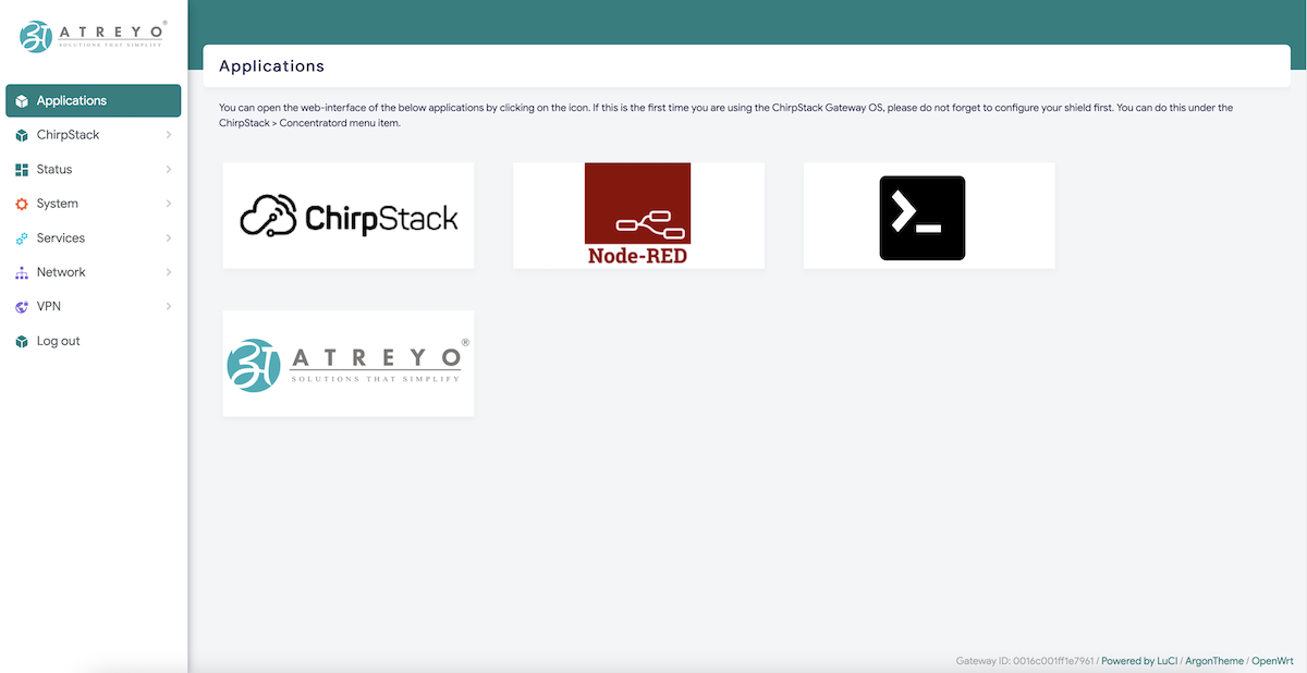
Chirpstack LNS and NodeRED and Terminal are pre-installed in the gateway.
If you are using the ChirpStack Gateway OS first time, do not forget to configure your shield first.
If you have a pop-up at the top with a message that no password has been set, set/change it.
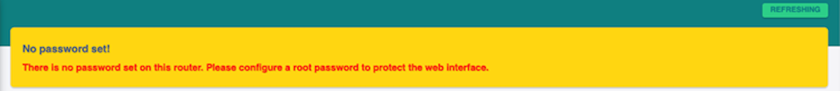
Set a password on the System>Administration page:
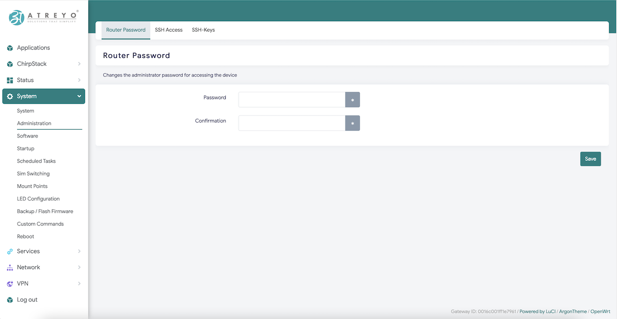
To maintain security, it is recommended to use long and complex passwords.
Chirpstack concentratord
ChirpStack Concentratord provides an unified API interface to LoRa(R) concentrator hardware. Please refer to the ChirpStack Concentratord Hardware page for supported hardware and configuration options.
This gateway has pre-installed chirpstack gateway OS and it has Chirpstack concentratord installed in it.
Basically it is used to configure respective shield (LoRa Chip) used in gateway.
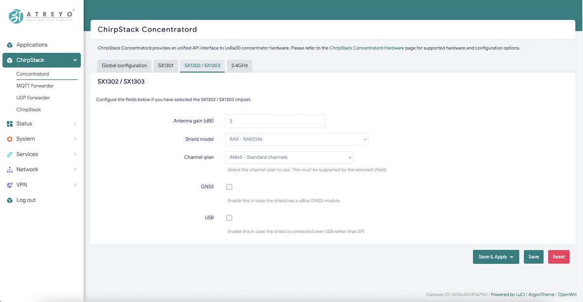
Antenna gain (dBi) , shield used in gateway, channel plan in which gateway should work ,etc, all these parameters can be configured in this section.
After shield setup gateway can be configured to in two different mode to send data 1) Chirpstack UDP forwarder and 2) Chirpstack MQTT forwarder.
Chirpstack forwarder
Gateway has inbuilt functionality pre-installed for ChirpStack Concentratord, in which one can setup shield and it's operating region.
The gatewat is supported with
- Chirpstack UDP forwarder
- Chirpstack MQTT forwarder
Chirpstack UDP forwarder:
If your your LNS server is handling UDP Data then you need to configure LNS in UDP forwarder mode.
Follow below basic steps to send data to UDP forwarder.
Open Chirpstack > UDP forwarder
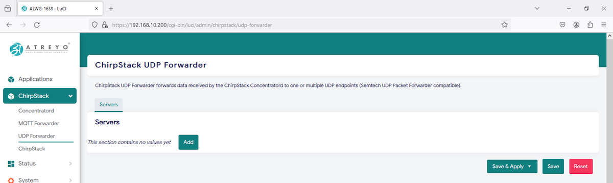
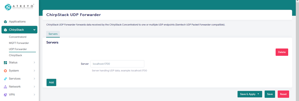
Add UDP server address along with port.
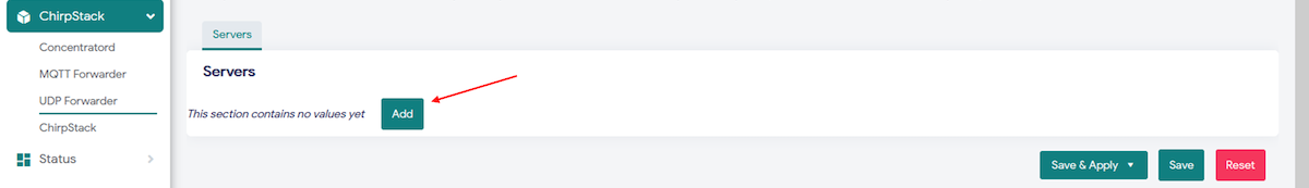
i.e.

Save the configuration.
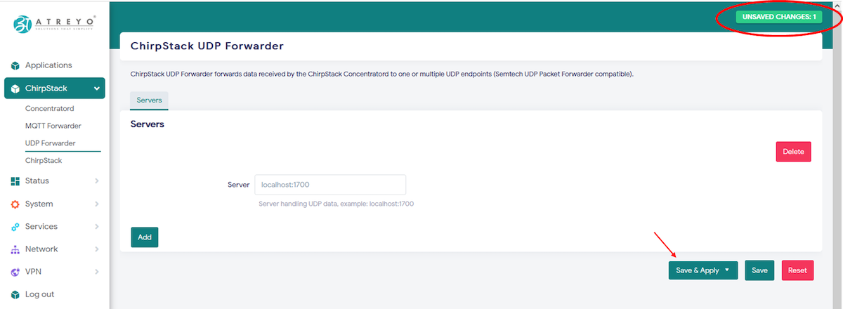
After adding LNS server you can see uplink forwarded to your UDP LNS server.
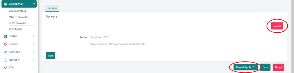
... in case need to delete UDP server, click the Delete button then Save & Apply
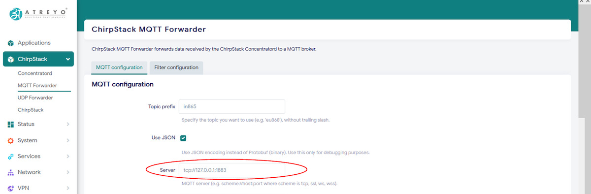
Chirpstack MQTT forwarder
If your your LNS server is handling Data over MQTT then you need to configure LNS in MQTT forwarder mode.
Follow below basic steps to send data to MQTT forwarder.
Open Chirpstack > MQTT forwarder
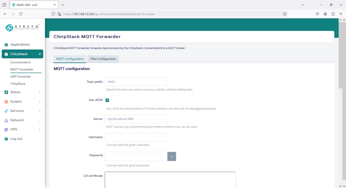
Add MQTT server address along with port.
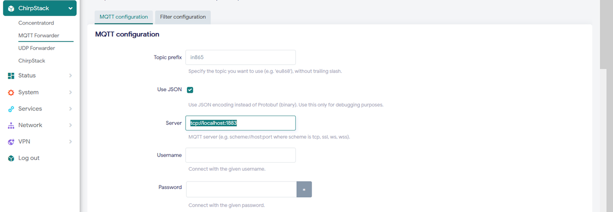
Topic prefix is by default from frequency , you can change it or keep as it is.
MQTT server is in this format --> e.g. scheme://host:port where scheme is tcp, ssl, ws, wss, so add your address accordingly (ignor address in picture)
You can provide user, password to connect if you MQTT server is defined in that way.
See how to configure gateway to send uplink/data to internal chirpstack LNS
Moreover you can add CA certificate, TLS certificate, and TLS key-file if needed.(copy paste the file contains, neither path to write or nor file you need to drag here).
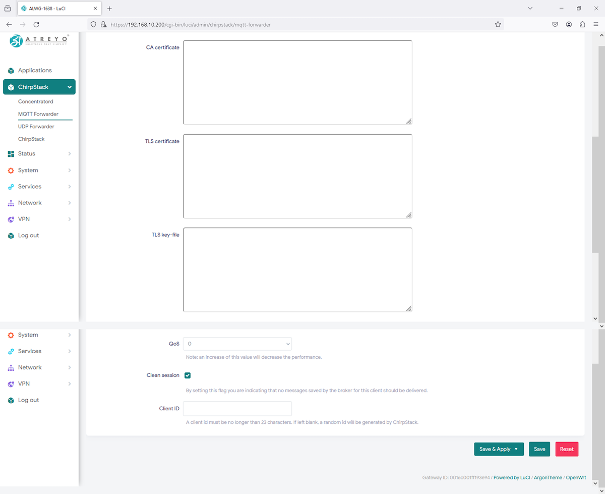
After adding configuration Save & Apply.
Uplink and Join-requests can be filtered based on the configured DevAddr prefixes and JoinEUI prefixes.
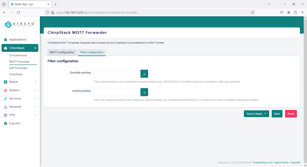
Once all configuration done, you can move to LNS server for further integration over cloud.
Chirpstack LNS
Refer Chirpstack MQTT forwarder in Chirpstack forwarder for basic idea to configure MQTT forwarder, When you open Chirpstack > MQTT forwarder add internal LNS server:port in Server and Save.
Read chirpstack documentation for MQTT forwarder, where MQTT server="tcp://127.0.0.1:1883" for connecting gateway to internal chirpstack LNS.
After adding server and saved it, gateway backend system will reset concentratord modulue to apply new configuration, System Log feature can have this information as shown below.
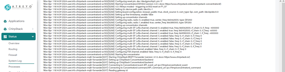
Once it has been reset/restarted succesfully, it will start functioning normally.
Gateway configuration is all set to move ahead into LNS configuration.
As like NodeRED, Chirpstack LNS is pre-installed in system as well as can be opened from same Applicaiton menu by clicking the icon or "<gateway_IP>:8080".
 Chirpstack will ask credential to login into chirpstack console.
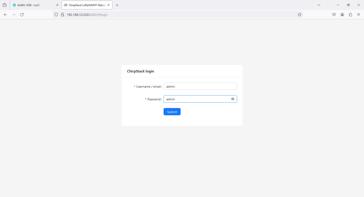
Credentials : user/pass --> admin/admin , Make sure to change it later for security purpose.
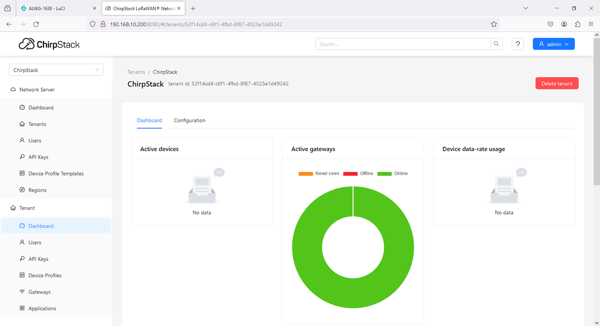
After login you will be redirected to Dashboard, where you can see gateway and end devices online/offline status, device dat-rate usage as well as Gateway Map.
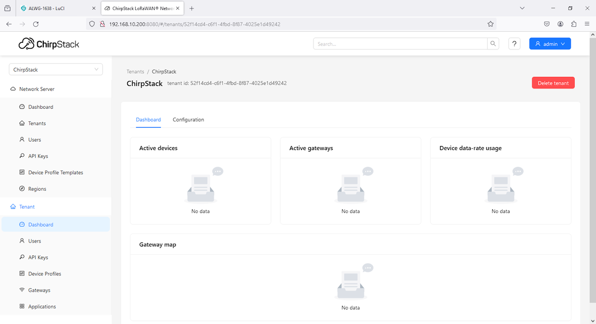
in above data there in No Data, as no Gateways/Devices has been added.
Cellular modem
Modem
The Gateway in its basic configuration is equipped with an LTE modem that also supports GPRS and SMS functions. Different modems were used depending on the model variant. Here is a table of models.
SIM card
The Gateway supports two microSIM cards, both 1.8V and 3V. The card connector is a push-pull type. When installing the SIM card, pay attention to the correct insertion of the card, and it's direction.
Refer to the below image for the SIM insertion guide.

Activate Cellular Network
To activate the LTE modem, go to Network > Interfaces and select the 3g-wan tab there.
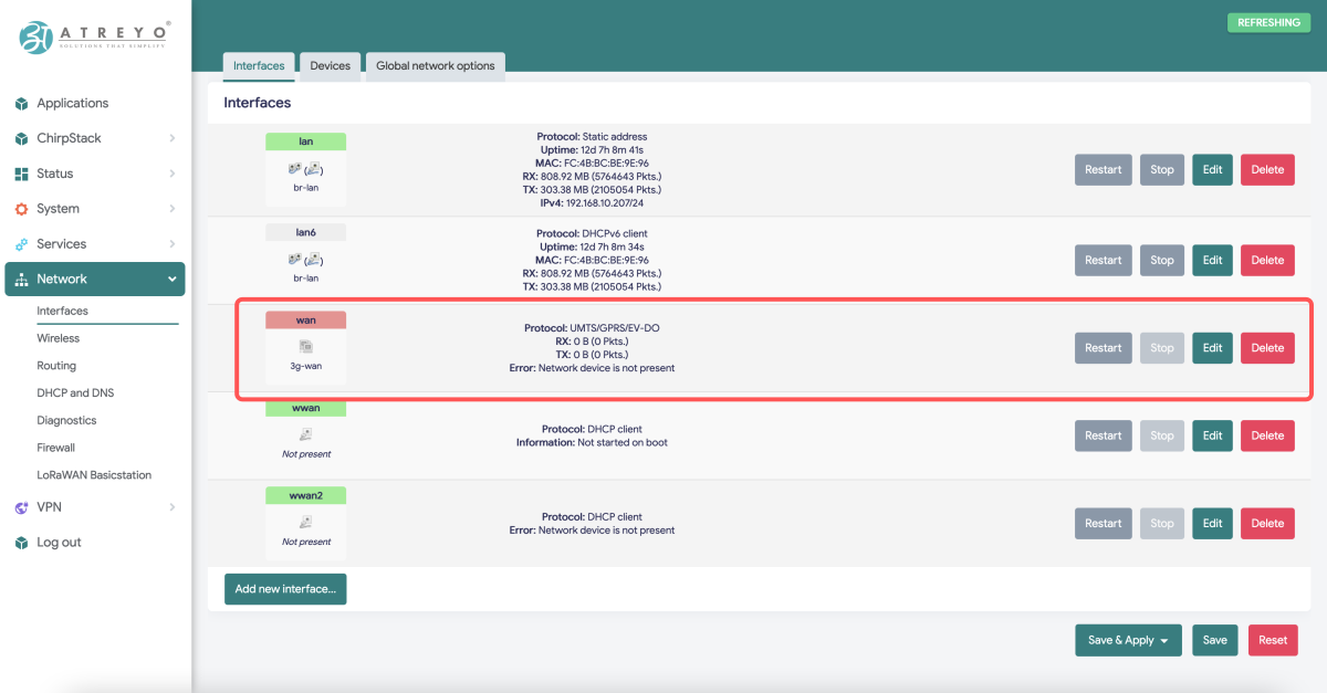
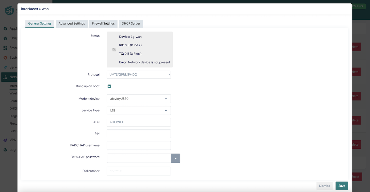
The interface is pre-configured but you might need to provide/change the network operator's APN, sometimes it also requires a username and password. Enter the required data and save.
Click the Edit button and enter APN.
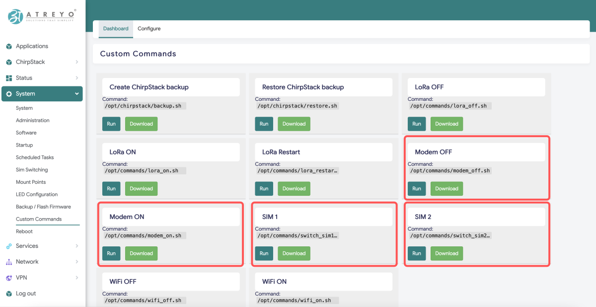
Then go to System > Custom Commands.
Here you will find below highlighted 4 scripts that are related to cellular modems.
- Modem ON - To give power to the cellular modem to use it.
- Modem OFF - To power down the cellular modem.
- SIM 1 - By default SIM 1 will be operated, still by this script SIM 1 can be operated.
- SIM 2 - To switch to SIM 2.
Once the script is successful you will get a pop-up at top right corner (Ref image below).

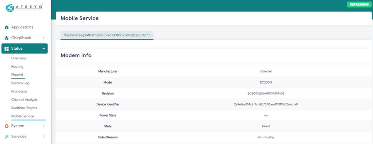
The modem will start up and connect to the Internet. To check if it is working properly and what the signal is, go to Status > Mobile Service.
Cellular modem power ON at boot
To make the gateway automatically connect to the GSM Internet after startup, you need to add a modem startup in the System > Startup section under Local Startup, and add script path before 'exit 0'.
/usr/commands/modem_on.sh Then save the changes.
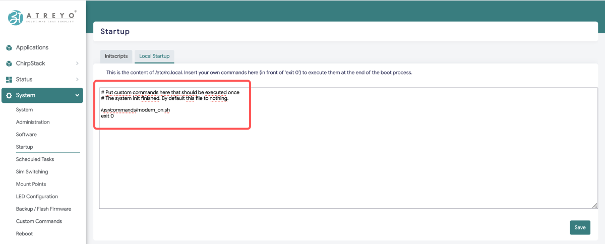
After each reboot, the gateway will automatically start the modem and connect to the GSM network.
Terminal
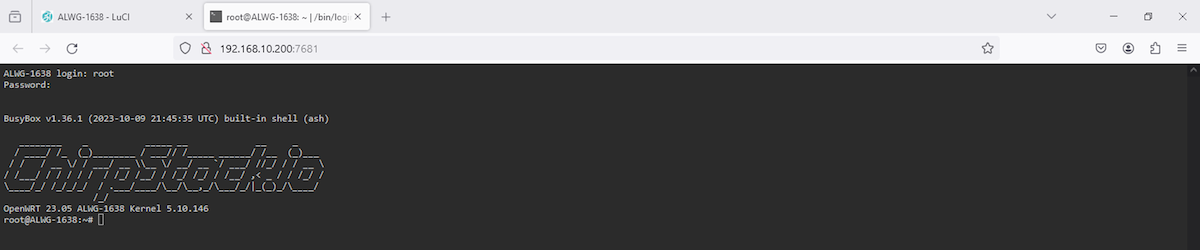
Few Gateway configuration need to be done using CLI or some backend files need to be edited or for any CLI based operation we need terminal, Hence same as NodeRED you can click on Terminal icon and it will open terminal in new tab or you can directly open in browser by "<gateway_IP>:7681"
After clicking icon terminal will open in new tab and ask for user/password , it's same as gateway login.
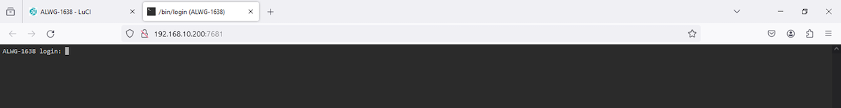
Credentials --> user/pass : root/root
Now CLI utility can be used for any specific purpose.
Chirpstack LNS
Once the Chirpstack LNS has been configured in gateway side, few things to be done in Chirpstack console. i.e. to add Gateway, End devices, Application etc.
to Add gateway in chirpstack LNS open chirpstack LNS by clicking the icon in Application.
Login pop-up will appeare, use admin/admin as user/pass. After login the screen will be like:
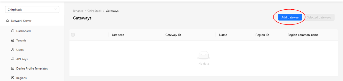
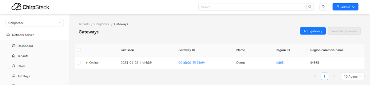
Go to Gateway section in Tenant to add perticular gateway.
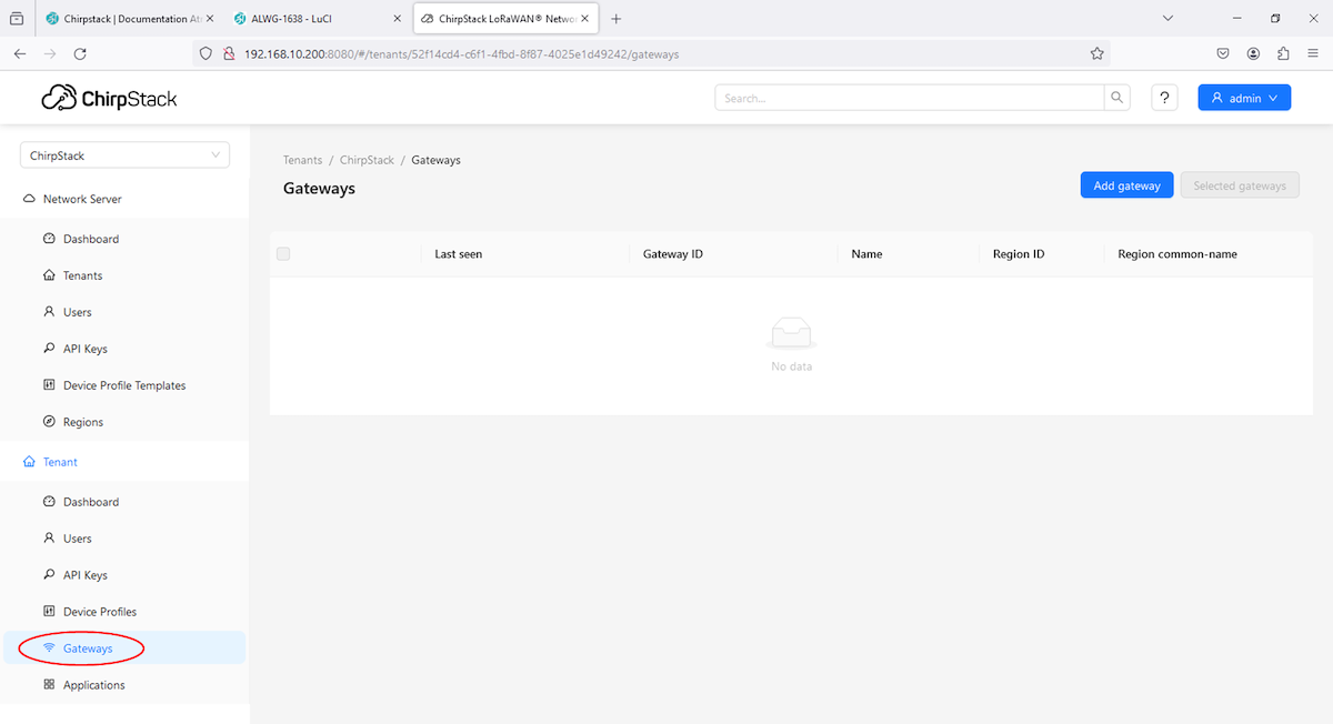
Click on Add gateway button.
It will open another page and ask for Gateway Name, it's EUI and any description you want to add for sack of your application purpose.
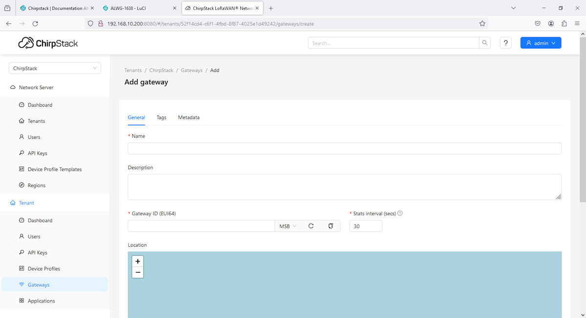
You can add data as per need and Submit.

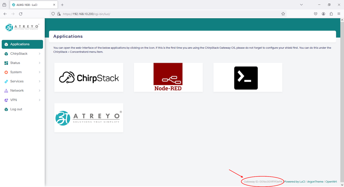
Makesure to findout Gateway ID from gateway webUI as shown in below image.
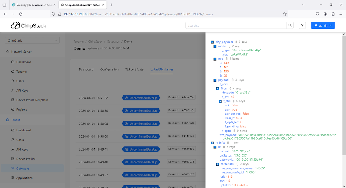
After submitting all the data pop-up at upper right side will shown to confirm that gateway has been added succesfully. and it will open page where you can see Dashboard, it's configuration as well as option to see loraWAN frames.
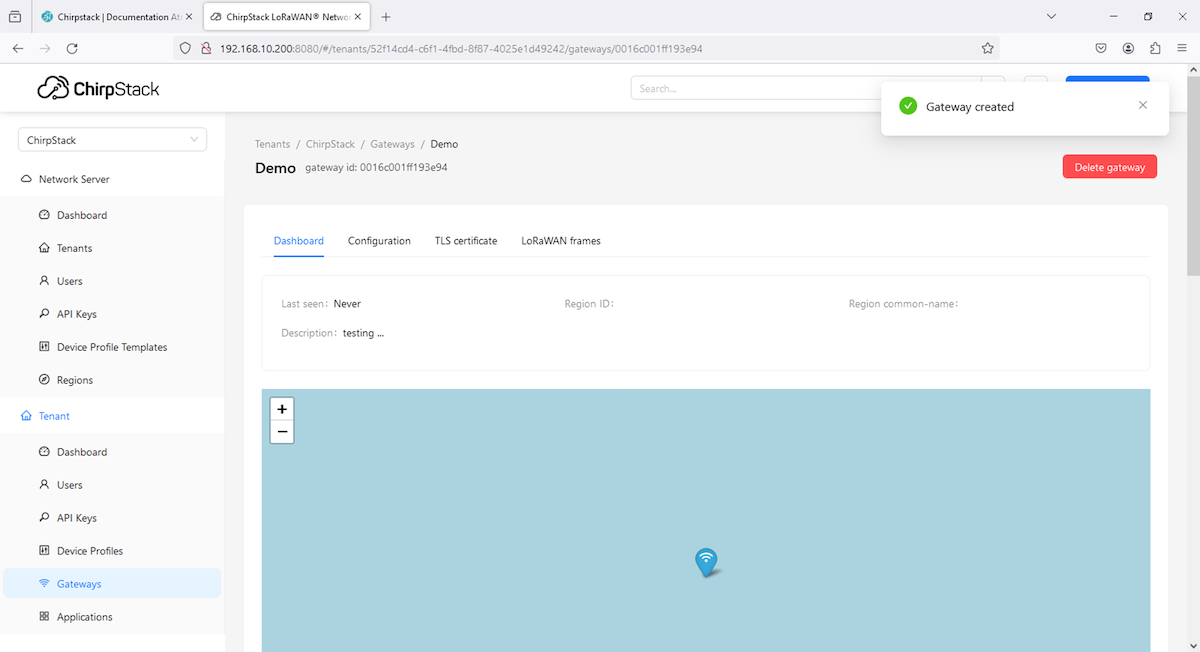
Last seen will change in a while as well as GPS will be fetched from gateway itself , also the metadata will be fetch from gateway.
Gateway status is also visible in Dashboard section as well as in Gateway section.
Click on Gateway ID to open Gateway ... (last seen and GPS has been updated after a while).
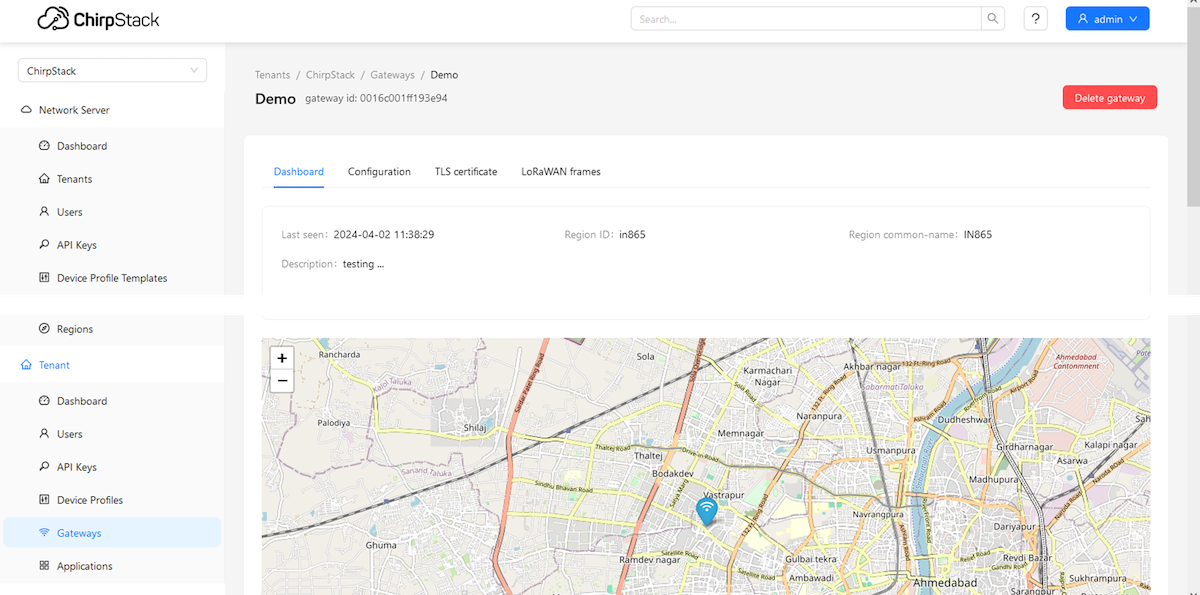
To change configuration or edit anything got to Configuration tab, you can add tag for easy tracebility in Tag tab under Configuration tab as well as gateway metadata will be fetched as shown below.

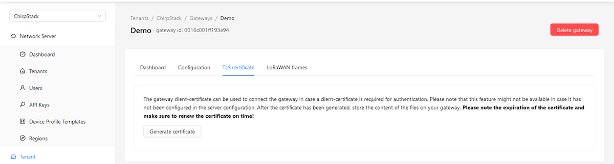
In TLS certificate tab you can generate TLS certificate for specific application.
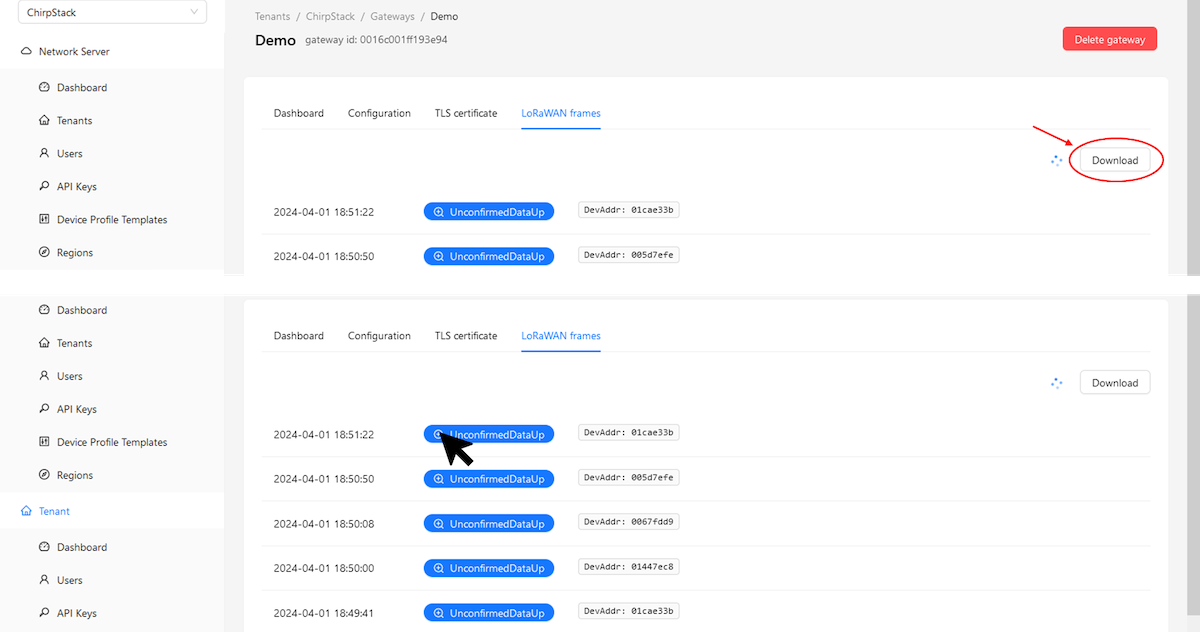
Once can download by clicking on Download button or open another sidebar to view event by clicking on event.
Node-RED
NodRED functionality is pre-installed and it has been hosted on 1880 port.
To access NodeRED use icon in Application section or open browser and hit "<gateway_IP>:1880"
New tab will open and and it might pop-up for user/pass if you are using it either first time or after long.
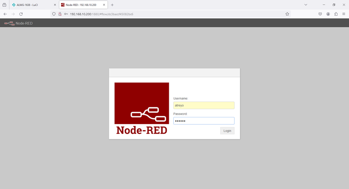
Credentials : user/pass --> atreyo/atreyo
After loggin in either you will have blank flow or any example flow saved by atreyo testing team.
1.
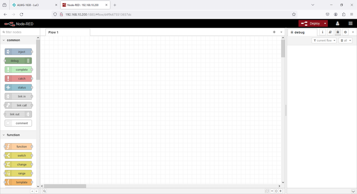
2.
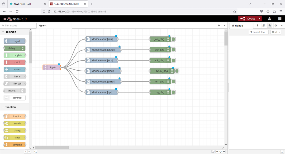
Above example flow is designed to fetch events of end devices, this flow will provide join, status, uplink, etc, events in debug.
To retrive data from events one should write function in NodeRED, then data can be send to external platforms.
Use cases/ Examples
Application
- City and Industry LoraWAN applications
- Smart Street Light, Energy meters, water meters, and other meter applications

Firmware releases
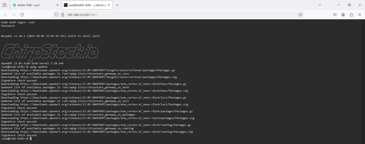
The Gateway works on the OpenWRT operating system. The operating system is specially prepared and compiled for hardware. So when it is booted up, it is ready for use. In addition to the pre-installed application, we provide our own repository of free apps compiled for this Gateway. We update the system regularly to keep the latest version. You can check the latest releases here.
| OpenWRT system | ChirpStack | Kernel version | Compilation date |
| 23.05 | 4.3.0 | 5.10.146 |
Safety information
Operating environment
- The device is designed to be installed in clean, dust-free and insect-free places
- Operating temperature: -25 ~ 65°C (-13 ~ 149°F).
- Humidity range is 10% to 95% (non-condensing). Use the device in a dry environment.
- Away from heat sources and direct sunlight.
- It must not be exposed to acid fumes, salts and other chemicals.
- The device must not be used in places where there is a risk of gas explosion.
Use in inappropriate conditions may damage the device or shorten its life.
Electrical and power supply safety
- The device is powered by PoE with a voltage in the range of 38-58V. Voltage up to 24V is considered safe. Be especially careful when supplying them with higher voltages.
- The device has the ability to control the output with the mains voltage of 160V. In this case, it is especially necessary to observe the safety rules during installation.
- Use only approved accessories
- Use the supplied power adapter or a good quality certified power adapter with the correct supply voltage range and sufficient power.
- Only use approved accessories like antenna etc.
Only a person with qualification and appropriate knowledge should install the device.
Malfunctioning and damaged device
- Do not disassemble the device.
- Only qualified personnel must service or repair the device or its accessories.
- If water or other liquid has got into the device, or if it looks mechanically damaged, do not connect the device, but take it to an authorized service center.
Radio frequency exposure
This device has been designed and manufactured not to exceed radio frequency energy emission limits set by regulatory agencies. To comply with RF exposure guidelines, the device must be used at least 20 cm away from a person's body. Failure to follow these instructions may result in exceeding the applicable RF exposure limits. This only applies to models with a built-in LTE modem.
What to do and what not to do
- You are solely responsible for the use of the device and any consequences of its use.
- Do not store or use the device in harsh environments such as dust, gases, oils, chemical vapors and damp places.
- Do not throw the device and its accessories. Handle with care.
- The device heats up during operation. Ensure proper ventilation.
- If you need to dispose of your device, check your local regulations for recycling and disposal of electronics.
- Route power, Ethernet, and antenna cables properly so that they cannot be accidentally pulled out.
- The device should be used and kept away from small children.