AM-201
AM-201 is LTE modem for use in industrial environment. It communicate to host by USB, RS485 and RS23. It can be used with operating systems such as Windows and Linux. For use in IoT systems, industrial control systems, control panels and distribution systems, public display controllers, remote monitoring for agriculture, industry and IoT.
General information
| Download technical specification | Technical Specification |
Model selection
Different modem models are available depending on the periphery availability and type.
| Model |
Cellular Network |
|||
| GPRS | 3G | LTE 4G | GNSS | |
| AM-201-IN | √ | √ | √ | |
| AM-201-GL | √ | √ | √ | √ |
Hardware
The Gateway is made on one PCB, which is fitted to the aluminum housing. The housing is made of a thick, strong aluminum profile with two end plates also made from aluminum. The surface of the housing is finished by anodizing.
At the bottom of the housing there are slots through which DIN rail clamp or any other clamp can be mounted by t-nuts.
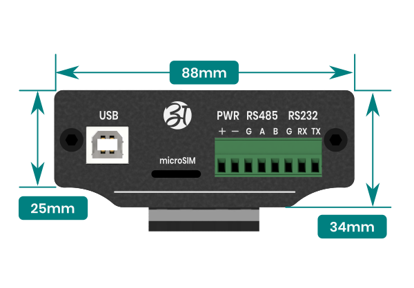
Front view dimensions
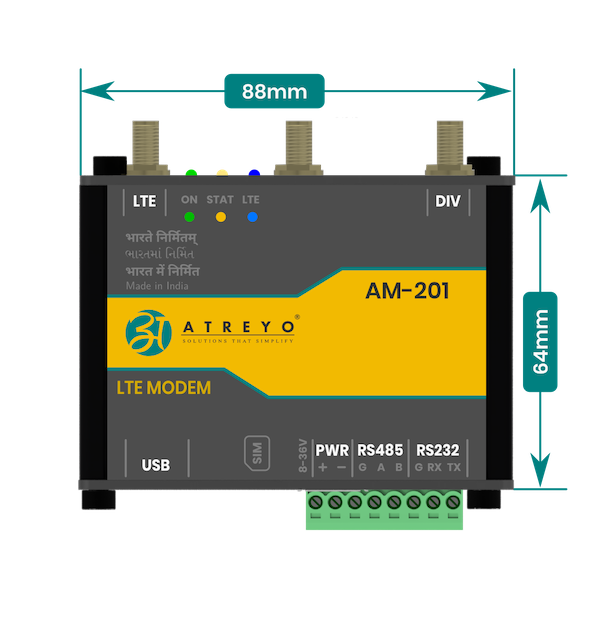
Side view dimensions
Interfaces
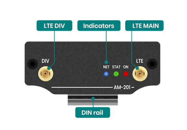
Top connector and indicators
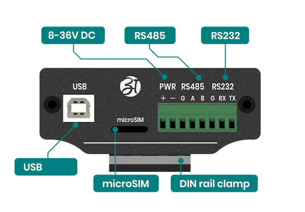
Bottom connector
Configuration manual
First start
After unpacking, the modem is ready to use. The modem can be connected to the target system using one of the following interfaces.
- USB
- RS485
- RS232
Only one interface can be used at a time. The modem requires power supply, and even with a USB connection, a power supply is necessary. It is not powered from the USB port.
Power supply
The device can be powered by connecting a power source to the terminal block:
- Loosen or remove the screws on the terminal block.
- Connect a 8–36 VDC power line to the terminal block.
- Tighten the connections, using the screws on the terminal block.
- Turn on the power source.
Note that the device does not have an on/off switch. It automatically turns on when it receives power. It takes a couple of seconds for the system to boot up. Once the system is ready, the RED LED will light up.
Power terminal block pin assignments are shown below:
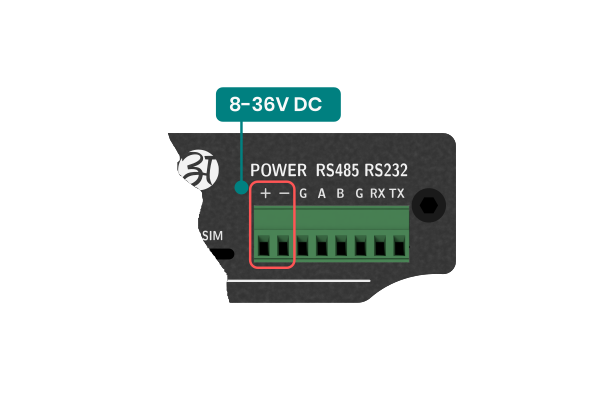
Inserting SIM card
Please refer drawing for proper SIM placement.
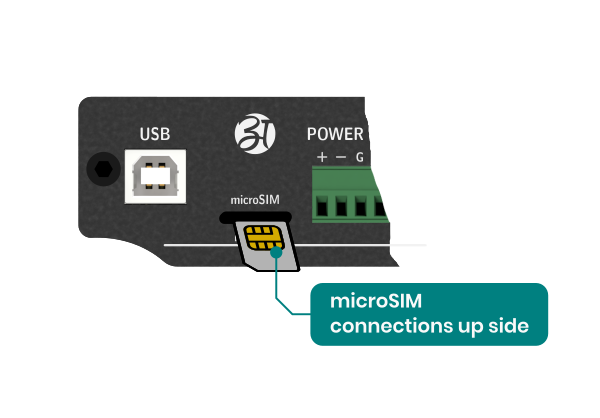
If by mistake you insert the card backwards then the card will be able to insert, but the modem will not work properly.
Connecting a modem via USB
To connect the modem via USB, it is necessary to connect with a USB A > B cable. This type of cable is often called a "printer cable". In addition to USB, it is necessary to connect a power supply in the range of 8-36V DC .
Connect according to the following diagram.

Connect in Windows operating system
To connect the modem via USB on Windows operating system, it is necessary to install the modem drivers. You can download the modem drivers at the bottom of this page. After successful installation, create a new Dialup connection.
Download: Windows_USB_Driver_V2.2.2.zip
Connecting modem via serial interface
he AM-201 can be used with either an RS485 or RS232 serial interface. To control the modem it is necessary to use AT commands. Regardless of the type of serial interface, the commands are the same.
Connecting a modem via RS485
To connect the modem to the device via RS485 serial interface, connect according to the following diagram.

Always connect the modem's A signal to the host's A signal, and the modem's B signal to the host's B signal. Most of the time it is not necessary to connect the common ground, or G, signal, but it is good practice to connect it.
Connecting a modem via RS232
To connect the modem to the device via RS232 serial interface, connect according to the following diagram.
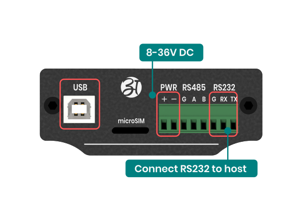
Remember that the modem's RX signal is combined with the host's TX signal, and the modem's TX signal is combined with the host's RX signal. That is, the signals are crossed. It is also necessary to connect common ground, or G.
Connect on startup - Windows
In many applications, it is necessary for the modem to start as soon as Windows starts. To do this, follow the steps below:
This instruction applies when using the modem via USB with Windows 10 operating system.
Step-1: Go to Network & Internet:
- In the Settings window, click on "Network & Internet."
- In the Network & Internet settings, select "Network and Sharing Center" from the menu.
- In the Network & Internet settings, select "Network and Sharing Center" from the menu.
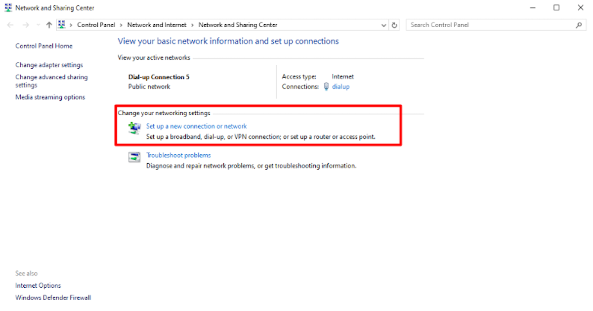
Step-2: Set Up a New Connection:
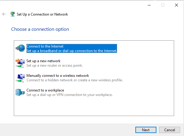
- Click on "Set up a new connection or network."
- The "Set up a connection or network" wizard will open. Choose "Connect to the Internet" and click "Next."
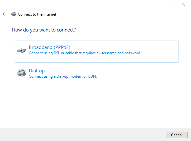
- Select "Set up a dial-up connection" and click "Next."
- Select “Dial-up” connect.
Enter the phone number provided by your Internet Service Provider (ISP) into the "Dial-up phone number" field.
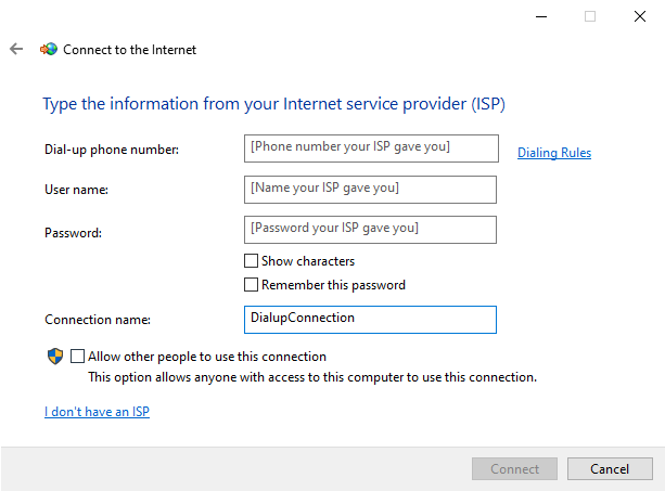
- Enter "Connection name" for your reference to connect network. Here, enter “Dial-up Connection”
- If required, Enter the username and password provided by your ISP.
- Check the box to remember your credentials if you don't want to enter them every time you connect.
- Click "Connect" to finish setting up the connection.
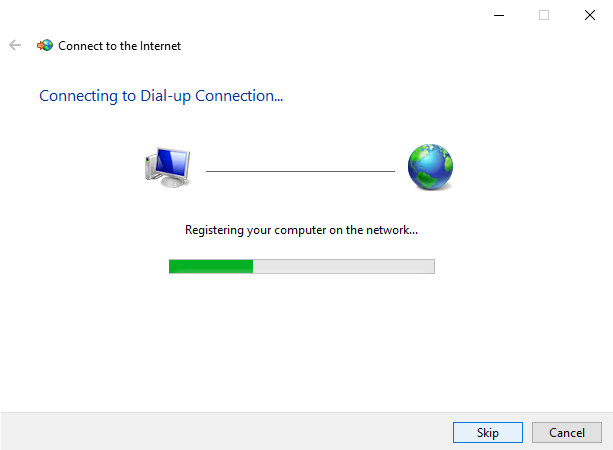
In case of a successful connection to the internet you will be presented with the option to browse the internet now.
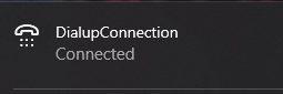
- Now, you can see your new connection if you click on the network icon located on the task bar.
Step-3: Creating a batch file for auto connect at startup:
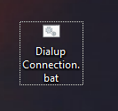
- Create New text document and name it as you given name in connection name.
- You need to change the extension of the file. Change it to .bat which will convert the file into a system batch file from which windows can execute commands. Here, create a file name as Dial-up Connection.bat.
Now, Edit the batch file and write below code:
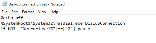
- Change yourusername and yourpassword with your actual username and password for the connection. You could also change Dial-up Connection with name of the connection name you created.If not required username and password then not need to write here.
- Save the file and exit from file.
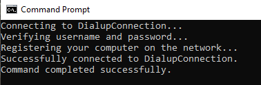
- Now, double click the bat file and see if the connection is established or not.
Step-4: Setting the batch file to run automatically
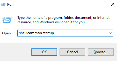
- To do this, first you have to lunch the Run prompt. By clicking, window+R.
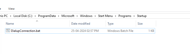
- Type shell:common startup – for opening the startup folder. This will only work if the network connection you created has been available to all users.
- To enable the bat file automatic startup, copy the created bat file in this folder.
- You can check that the bat file that you have placed in the startup folder will run by lunching Task manager and going to the startup tab.
- It’s done. Restart your system to see it works.
Safety information
Operating environment
- The device is designed to be installed in clean, dust-free and insect-free places
- Operating temperature: -25 ~ 65°C (-13 ~ 149°F).
- Humidity range is 10% to 95% (non-condensing). Use the device in a dry environment.
- Away from heat sources and direct sunlight.
- It must not be exposed to acid fumes, salts and other chemicals.
- The device must not be used in places where there is a risk of gas explosion.
Use in inappropriate conditions may damage the device or shorten its life.
Electrical and power supply safety
- The device is powered with a voltage in the range of 8-36V. Voltage up to 24V is considered safe. Be especially careful when supplying them with higher voltages.
- Use only approved accessories
- Use the supplied power adapter or a good quality certified power adapter with the correct supply voltage range and sufficient power.
- Only use approved accessories like antenna etc.
Only a person with qualification and appropriate knowledge should install the device.
Malfunctioning and damaged device
- Do not disassemble the device.
- Only qualified personnel must service or repair the device or its accessories.
- If water or other liquid has got into the device, or if it looks mechanically damaged, do not connect the device, but take it to an authorized service center.
Radio frequency exposure
This device has been designed and manufactured not to exceed radio frequency energy emission limits set by regulatory agencies. To comply with RF exposure guidelines, the device must be used at least 20 cm away from a person's body. Failure to follow these instructions may result in exceeding the applicable RF exposure limits. This only applies to models with a built-in LTE modem.
What to do and what not to do
- You are solely responsible for the use of the device and any consequences of its use.
- Do not store or use the device in harsh environments such as dust, gases, oils, chemical vapors and damp places.
- Do not throw the device and its accessories. Handle with care.
- The device heats up during operation. Ensure proper ventilation.
- If you need to dispose of your device, check your local regulations for recycling and disposal of electronics.
- Route power, Ethernet, and antenna cables properly so that they cannot be accidentally pulled out.
- The device should be used and kept away from small children.