# Configuration manual
#### Wiring
The expander has opto-isolated inputs that require an external power supply. This requires a 8-36V power supply. The inputs can be driven by both positive and negative signals. Both examples are shown in the attached diagram.
The outputs of the expander are directly connected to the relay leads. The relays are of normal open type.
#### NPN wiring example
[](https://docs.atreyo.in/uploads/images/gallery/2025-09/KQ3amb-12i-4o-wiring-01.png)
#### PNP wiring example
[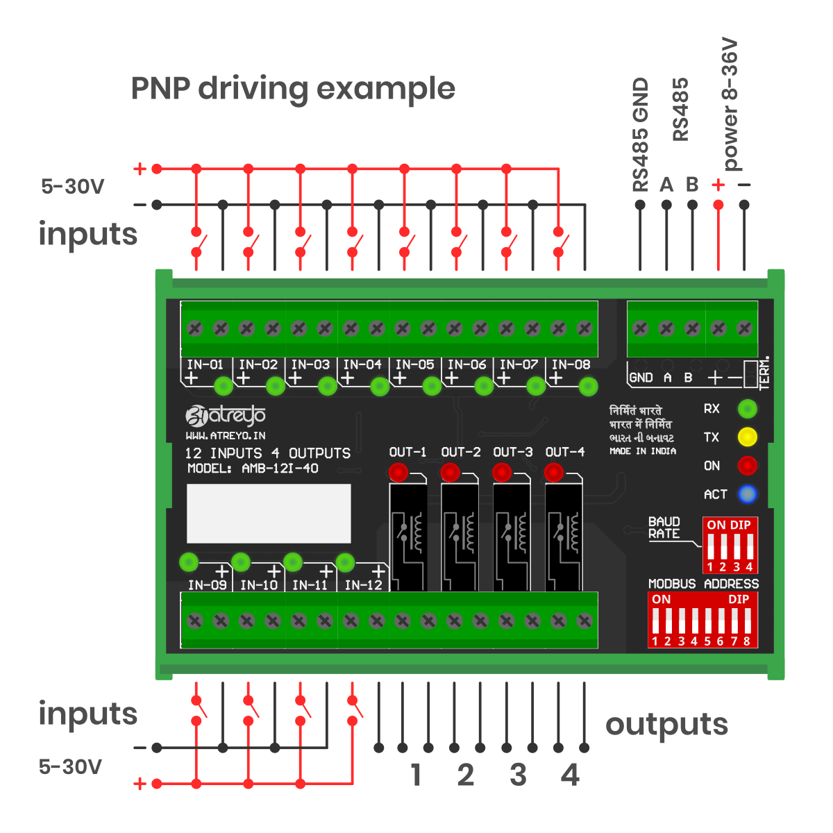](https://docs.atreyo.in/uploads/images/gallery/2025-09/axVamb-12i-4o-wiring-02.png)
It is possible to combine any input in any mode. One can be NPN and the other PNP, as all inputs are independent.
---
#### Protocol Description
Modbus Protocol is a messaging structure, widely used to establish master-slave communication between intelligent devices. A Modbus message sent from a master to a slave contains the address of the slave, the 'command' (e.g. 'read register' or 'write register'), the data, and a check sum (LRC or CRC).
Since Modbus protocol is just a messaging structure, it is independent of the underlying physical layer. In AMB-4I-4O is implemented using RS485 interface.
##### MODBUS RTU Framing
The AMB-4I-4O module supports standard RTU Modbus protocol for getting the input status and setting/getting the relays status. RTU Modbus Protocol frame is illustrated below:
| Start | Address | Function | Data
| RC Check | End
|
| ≥ 3.5 Char | 4 Bits | 8 Bits
| N\*8 Bits | 16 Bits | ≥ 3.5 Char |
- **Start** is at least 3.5 char time of silent interval between master and slave to start communication
- **Address** is a slave ID Address
- **Function** is the function code of Modbus protocol
- **Data** is the appropriate data for function code
- **CRC** is Cyclic Redundancy Check for Error Checking (here, CRC-16,Big Endian(ABCD))
- **End** is at least 3.5 char time of silent interval between master and slave to start communication
##### MODBUS Serial Port Parameter
| Parameter | Option/range |
| Baudrate | 9600 – 128000 configurable |
| Data bit | 8
|
| Parity | None |
| Stop bit | 1 |
##### ID Configuration of MODBUS Card
After setting Modbus and baudrate, the I/O card must be restarted by switching the power off and on.
User can set the slave ID address using 8 Bit DIP switch found on board. This allow 0 to 255 different IDs to be set. The number below the switches are added together and the result will be identifier of the device slave ID.
To set the slave ID 125, you need to turn ON switch 1,3,4,5,6,7 on DIP switch and OFF the others (In this, convert slave ID number 125 into 8bit binary form – 01111101, turn ON DIP switch 1,3,4,5,6,7 and turn OFF DIP switch 2,8) and so on….
[](https://docs.atreyo.in/uploads/images/gallery/2025-03/amb-4i-4o-dip.png)
Address 1–247 → valid slave IDs for individual devices
Address 0 → reserved for broadcast messages; all slaves receive it but no one replies
Addresses 248–255 → reserved/unassigned (not permitted for standard device addressing)
##### Baudrate Configuration of MODBUS
User can set the baudrate using 4 Bit DIP switch found on board. To set baudrate, first turn off power supply of card. This allows to set baudrate between 2400bps to 128000bps as shown below table.
| Baudrate | SW1 | SW2 | SW3 | SW4 |
|---|
| 9600 | OFF | OFF | OFF | OFF |
| 2400 | ON | OFF | OFF | OFF |
| 4800 | OFF | ON | OFF | OFF |
| 14400 | OFF | OFF | ON | OFF |
| 19200 | OFF | OFF | OFF | ON |
| 28800 | ON | ON | OFF | OFF |
| 38400 | OFF | ON | ON | OFF |
| 57600 | OFF | OFF | ON | ON |
| 115200 | ON | OFF | OFF | ON |
| 128000 | ON | ON | ON | ON |
---
#### Modbus RTU Commands
The following commands (functions) were implemented in the Modbus RTU AMB-4I-4O.
- 01 (01 hex) Function code – Read Coils
- 02 (02 hex) Function code – Read Discrete Inputs
- 05 (05 hex) Function code – Write Single Coil
- 15 (0F hex) Function Code – Write Multiple Coils
Coils are mapped to outputs and discrete inputs are mapped to inputs. Coils read/write output status and discrete inputs read Input status. There are 12 inputs for reading-input 0 to input 11 which refer to input 1 to input 12 and coil 0 to coil 3 which refer to output 1 to output 4.
Note: For all below example, consider slave address – 0x01 will change with 8bit DIP switch.
---
##### 01 (01 hex) Function Code – Read Coils
Read Coils command is requesting the ON/OFF status of coils. Read Coils command will return individual current outputs status. Also Read Coils Command will return sequentially outputs current status.
Example of how to read output status are given below:
REQUEST FRAME –
**01 01 0000 0004 3DC9**
**01** – The Slave Address (01 hex = 01)
**01** – The Function Code
**0000** – The Data Address of first coil to read (0000hex = coil 0)
**0004** – The total number of coils requested (0004hex = 4 coils – outputs))
**3DC9** – The CRC for error checking
RESPONSE FRAME –
**01 01 01 0A D18F**
**01** – The Slave Address (01 hex = 01)
**01** – The Function Code
**01** – The number of data bytes to follow (4 coils / 8 bits per byte = 1 byte)
**0A** – Coils 0 to 3(Output), 0A hex = 0000 1010 (0 – ON, 1 – OFF)
**D18F** – The CRC for error checking
---
##### 02 (02 hex) Function Code – Read Discrete Inputs
Read Discrete Inputs Command is requesting the ON/OFF status of Inputs. Read Discrete Inputs command will return individual current Input status. Also this Command will return sequentially Input current status.
Example of how to read Inputs status are given below:
REQUEST FRAME -
**01 02 0000 000C 780F**
**01** – The Slave Address (01 hex = 01)
**01** – The Function Code
**0000** – The Data Address of first Input to read (0000hex = Input 0)
**000C** – The total number of Inputs requested (000Chex = 12 Inputs))
**780F** – The CRC for error checking
RESPONSE FRAME -
**01 02 02 5A09 3FD3**
**01** – The Slave Address (01 hex = 01)
**02** – The Function Code
**02** – The number of data bytes to follow (12 coils / 8 bits per byte = 2 byte)
**5A** – Input 7 to 0(Input), 5A hex = 0000 1010 (0 – ON, 1 – OFF)
**09** – Input 11 to 8(Input), 09 hex = 0000 1010 (0 – ON, 1 – OFF)
**3FD3** – The CRC for error checking
---
##### (05hex) Function Code – Write Single Coil
Write Single Coil (0x05) command will set single output(relay) ON or OFF.
Example of how to set Relay ON is given below:
REQUEST FRAME –
**01 05 0003 FF00 7C3A**
**01** – The Slave Address (01 hex = 01)
**05** – The Function Code
**0003** – The Data Address of coil to change status (0003hex = coil 3)
**FF00** – The Status to write (FF00 – ON relay, 0000 – OFF relay)
**7C3A** – The CRC for error checking
RESPONSE FRAME –
**01 05 0003 FF00 7C3A**
**01** – The Slave Address (01 hex = 01)
**05** – The Function Code
**0003** – The Data Address of coil to change status (0003hex = coil 3)
**FF00** – The Status written (FF00 – ON relay, 0000 – OFF relay)
**7C3A** – The CRC for error checking
---
##### 15 (0Fhex) Function Code – Write Multiple Coil
Write Multiple Coils command will set multiple sequential relays ON or OFF.
Example of how to set Relay1 to Relay4 with single command is given below:
REQUEST FRAME –
**01 0F 0000 0004 01 0A BE91**
**01** – The Slave Address (01 hex = 01)
**0F** – The Function Code
**0000** – The Data Address of first coil(0000hex = coil 0)
**0004** – The number of coils to written(04hex = Output 1 to 4)
**01** – The number of data bytes to follow
**0A** – 4 space holders & coils 0 – 3 (0000 1010)(0 – OFF, 1 – ON)
**BE91** – The CRC for error checking
RESPONSE FRAME –
**01 0F 0000 0004 5408**
**01** – The Slave Address (01 hex = 01)
**0F** – The Function Code
**0000** – The Data Address of first coil(0000hex = coil 0)
**0004** – The number of coils to written(04hex = Output 1 to 4)
**5408** – The CRC for error checking
---
##### MODBUS Exception Codes
Exception responses from either the master or a slave can result from data processing errors.
One of the following events can occur after a request from the master:
- If the slave receives the request from the master without a communication error and can handle the request correctly, it returns a normal response.
- If the slave does not receive the request from the master due to a communication error, it does not return a response. The master program eventually processes a timeout condition for the request.
- If the slave receives the request from the master but detects a communication error, it does not return a response. The master program eventually processes a timeout condition for the request.
- If the slave receives the request from the master without a communication error, but cannot handle it (for example, the request is to read a register that does not exist), the slave returns an exception response to inform the master of the nature of the error.
Exception Frame:
| Sn. | Definition | Description |
|---|
| 1 | Slave Address | The Slave Address of requested slave |
| 2 | Exception Function Code | Requested Function Code + 128 (0x80) |
| 3 | Exception Code | See in next table |
| 4 | CRC check | The CRC for error checking |
Exception Codes:
| Exception Code | Name | Description |
|---|
| 0X01 | Illegal Function Code | The function code received in the request is not an allowable action for the slave. This may be because the function code was not implemented in the unit selected. |
| 0x02 | Illegal Data Address | The data address received in the request is not an allowable address for the slave. |
| 0x03 | Illegal Data Value | A value contained in the request data field is not an allowable value for the slave. This indicates a fault in the structure of remainder of a complex request, such as that the implied length is incorrect. |