# AMB-8I-4O Expander
The AMB-8I-4O input/output expander with Modbus RTU and IEC-60870-5-101 protocol support (under development). It has 8 isolated digital inputs with voltage range up to 30VDC and 4 relay output with 5A 230V range and NO contacts. The power supply range is 8 to 48V DC. The use of DC / DC technology for supplying relays enables a wide range of supply voltages.
Please read carefully before starting. Also read the product [safety information.](https://docs.atreyo.in/books/amb-8i-4o-expander/page/safety-information)
# General information
| Download technical specification | [Technical Specification](https://www.atreyo.in/sites/default/files/a-download/AMB-8I-4O%20Technical%20Specification.pdf) |
The AMB-8I-4O input/output expander with Modbus RTU and IEC-60870-5-101 protocol support. (under development). It has 8 isolated digital inputs with voltage range up to 30VDC and 4 relay output with 5A 230V range and NO contacts. The power supply range is 8 to 48V DC. The use of DC / DC technology for supplying relays enables a wide range of supply voltages.
---
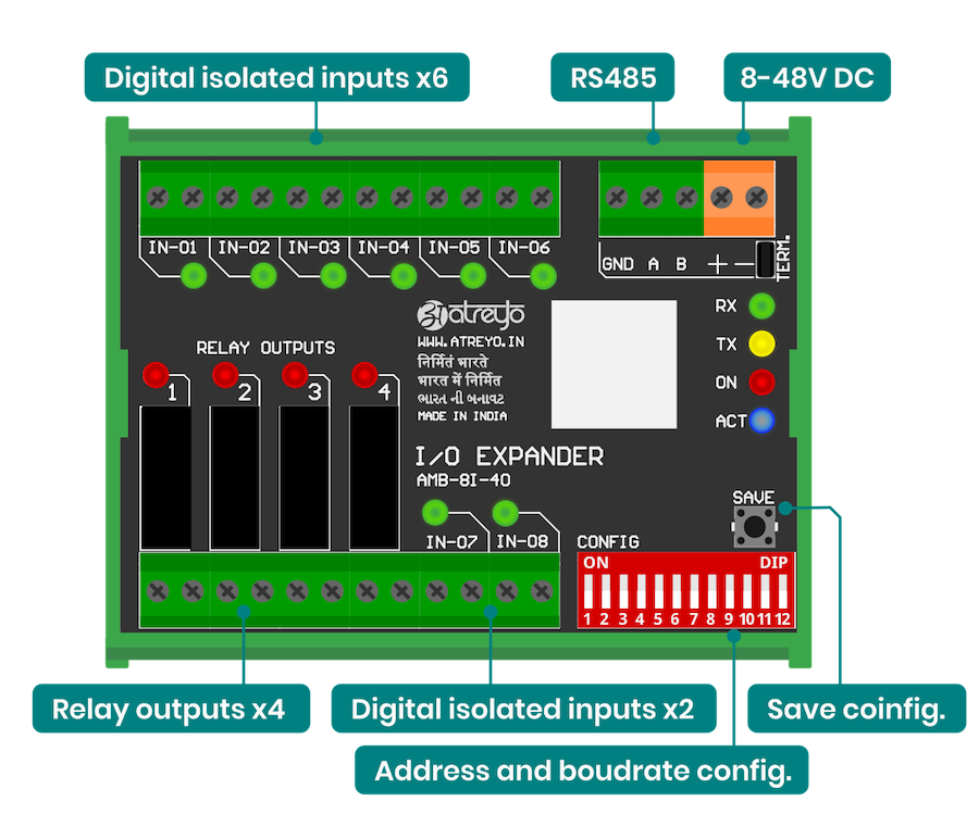
#### Connection information
Below is a description of the expander connectors. The outputs of the expander are directly connected to the relay leads. The relays are of normal open type.
---
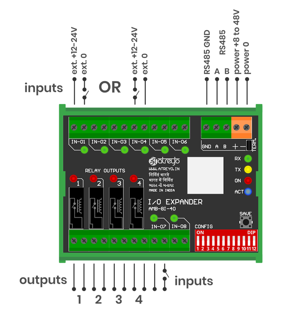
#### Wiring
The expander has opto-isolated inputs that require an external Voltage source in range of a 5-30V. The inputs can be driven by both positive and negative signals. Both examples are shown in the attached diagram.
The outputs of the expander are directly connected to the relay leads. The relays are of normal open type.
# Configuration Manual
Configuration
AMB-8I-4O is an I/O expander operating over Modbus RTU and IEC60870-5-101 protocol. The first DIP switch is used to switch between Modbus RTU and IEC modes. If it is in position 0, then the AMB is operating in Modbus RTU mode. If it is in position 1, then it works in the IEC protocol. As the two protocols have different functions, the DIP switch is also different. In IEC mode, the last DIP switch is used to change the operating mode from balanced/unbalanced. To save the DIP switch settings in the internal memory, the SAVE button must be pressed.
# Configuration IEC60870
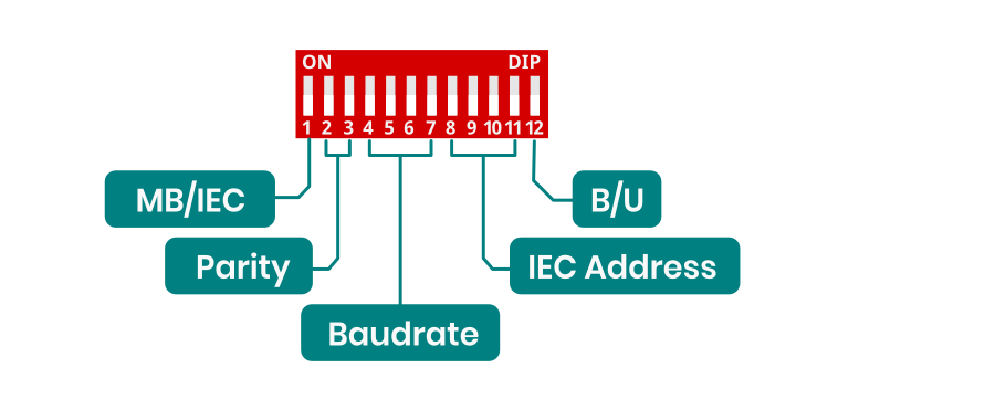
##### DIP switch configuration
This is DIP switch functions diagram for Modbus RTU configuration. For enable IEC60870 protocol 1 switch should be in ON position.
[](https://docs.atreyo.in/uploads/images/gallery/2025-03/amb-8i-4o-dip-2.png)
##### Parity configuration
Parity configuration for both Modbus and IEC.
| Parity | Function |
| 00
| NONE |
| 01
| ODD
|
| 10
| EVEN
|
| 11
| NONE |
---
##### Baudrate configuration
Baudrate configuration for both Modbus and IEC
| Switch | Baudrate |
| 0000
| 9600 |
| 0001
| 1200 |
| 0010
| 2400 |
| 0011
| 4800 |
| 0100
| 14400 |
| 0101
| 19200 |
| 0110
| 28800 |
| 0111 | 38400 |
| 1000
| 57600 |
| 1001
| 76800 |
| 1010
| 115200 |
| 1011
| 230400 |
| 1100
| 256000 |
| 1101
| 460800 |
| 1110
| 576000 |
| 1111
| 921600 |
---
##### Address configuration for IEC
| Switch | Value | IEC Address |
| 0000
| 0 | 1
|
| 0001
| 1 | 2
|
| 0010
| 2 | 3
|
| 0011
| 3 | 4
|
| 0100
| 4 | 5
|
| 0101
| 5 | 6
|
| 0110
| 6 | 7
|
| 0111 | 7 | 10
|
| 1000
| 8 | 20
|
| 1001
| 9 | 30
|
| 1010
| 10 | 40
|
| 1011
| 11 | 50
|
| 1100
| 12 | 60
|
| 1101
| 13 | 70
|
| 1110
| 14 | 80
|
| 1111
| 15 | 90
|
---
#### EC60870-5-101 Implementation Guide
##### Protocol Overview
The device implements IEC60870-5-101 protocol with the following key functions:
##### Reading States (Interrogation)
- C\_IC\_NA\_1 (100)
- Reading all inputs and outputs states
- Inputs: 1000-1007
- Outputs: 2000-2003
##### Controlling Outputs
- Function: C\_SC\_NA\_1 (45)
- Purpose: Setting individual output states
- IOA range: 2000-2003
- Values: ON (1) / OFF (0)
#### Command Structure
##### General Interrogation Command
```
Type ID: 100 (C_IC_NA_1)
Qualifier: 20
Cause of Transmission: 6 (Activation)
Common Address: 1
```
##### Single Command (Output Control)
```
Type ID: 45 (C_SC_NA_1)
Cause of Transmission: 6 (Activation)
Common Address: 1
IOA: 2000-2003
Value: 0/1
```
#### SCADA system configuration
##### IEC60870-5-101 Protocol Configuration
- Common Address (ASDU): 1
- Frame format: FT1.2
- Link Layer Address: according to device configuration
##### I/O Points Configuration:
For inputs (8 channels):
- Type: Single Point Information (M\_SP\_NA\_1)
- IOA addresses: 1000-1007
- Direction: Monitoring (read)
For outputs (4 channels):
- Type: Single Command (C\_SC\_NA\_1)
- IOA addresses: 2000-2003
- Direction: Control (write)
Verification:
- Check if input states are correctly read (IOA 1000-1007)
- Confirm control operation for each output (IOA 2000-2003)
- Verify device responds to General Interrogation
# Configuration Modbus
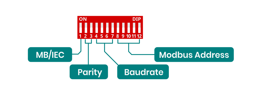
##### DIP switch configuration
This is DIP switch functions diagram for Modbus RTU configuration. For enable Modbus RTU protocol 1 switch should be in OFF position.
[](https://docs.atreyo.in/uploads/images/gallery/2025-03/amb-8i-4o-dip-1.png)
---
- ##### Baudrate configuration
Baudrate configuration for both Modbus and IEC
| Switch | Baudrate |
| 0000
| 9600 |
| 0001
| 1200 |
| 0010
| 2400 |
| 0011
| 4800 |
| 0100
| 14400 |
| 0101
| 19200 |
| 0110
| 28800 |
| 0111 | 38400 |
| 1000
| 57600 |
| 1001
| 76800 |
| 1010
| 115200 |
| 1011
| 230400 |
| 1100
| 256000 |
| 1101
| 460800 |
| 1110
| 576000 |
| 1111
| 921600 |
---
##### Address configuration for Modbus RTU
| Switch | Value | Modbus Address |
| 00000 | 0
| 1
|
| 00001 | 1
| 2
|
| 00010 | 2
| 3
|
| 00011 | 3
| 4
|
| 00100 | 4
| 5
|
| 00101 | 5
| 6
|
| 00110 | 6
| 7
|
| 00111 | 7
| 10
|
| 01000 | 8
| 20
|
| 01001 | 9
| 30
|
| 01010 | 10
| 40
|
| 01011 | 11
| 50
|
| 01100 | 12
| 60
|
| 01101 | 13
| 70
|
| 01110 | 14
| 80
|
| 01111 | 15
| 90
|
| 10000 | 16
| 100
|
| 10001 | 17
| 110
|
| 10010 | 18
| 120
|
| 10011 | 19
| 130
|
| 10100 | 20
| 140
|
| 10101 | 21
| 150
|
| 10110 | 22
| 160
|
| 10111 | 23
| 170
|
| 11000 | 24
| 180
|
| 11001 | 25
| 190
|
| 11010 | 26
| 200
|
| 11011 | 27
| 210
|
| 11100 | 28
| 220
|
| 11101 | 29
| 230
|
| 11110 | 30
| 240
|
| 11111 | 31
| 250
|
---
# Safety information
##### Operating environment
- The device is designed to be installed in clean, dust-free and insect-free places
- Operating temperature: -25 ~ 65°C (-13 ~ 149°F).
- Humidity range is 10% to 95% (non-condensing). Use the device in a dry environment.
- Away from heat sources and direct sunlight.
- It must not be exposed to acid fumes, salts and other chemicals.
- The device must not be used in places where there is a risk of gas explosion.
Use in inappropriate conditions may damage the device or shorten its life.
---
##### Electrical and power supply safety
- The device is powered with a voltage in the range of 8-48V. Voltage up to 24V is considered safe. Be especially careful when supplying them with higher voltages.
- Use only approved accessories
- Use the supplied power adapter or a good quality certified power adapter with the correct supply voltage range and sufficient power.
- Only use approved accessories like antenna etc.
Only a person with qualification and appropriate knowledge should install the device.
---
##### Malfunctioning and damaged device
- Do not disassemble the device.
- Only qualified personnel must service or repair the device or its accessories.
- If water or other liquid has got into the device, or if it looks mechanically damaged, do not connect the device, but take it to an authorized service center.
---
##### What to do and what not to do
- You are solely responsible for the use of the device and any consequences of its use.
- Do not store or use the device in harsh environments such as dust, gases, oils, chemical vapors and damp places.
- Do not throw the device and its accessories. Handle with care.
- The device heats up during operation. Ensure proper ventilation.
- If you need to dispose of your device, check your local regulations for recycling and disposal of electronics.
- Route power, Ethernet, and antenna cables properly so that they cannot be accidentally pulled out.
- The device should be used and kept away from small children.