# Configuration manual
#### Basic information
AMB-8I-4O is an I/O expander operating over Modbus RTU and IEC60870-5-101 protocol. The first DIP switch is used to switch between Modbus RTU and IEC modes. If it is in position 0, then the AMB is operating in Modbus RTU mode. If it is in position 1, then it works in the IEC protocol. As the two protocols have different functions, the DIP switch is also different. In IEC mode, the last DIP switch is used to change the operating mode from balanced/unbalanced. To save the DIP switch settings in the internal memory, the SAVE button must be pressed.
---
#### Configuration
##### DIP switch configuration
This is DIP switch functions diagram for Modbus RTU configuration. For enable Modbus RTU protocol 1 switch should be in OFF position.
[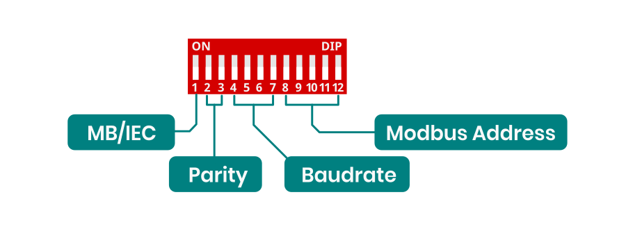](https://docs.atreyo.in/uploads/images/gallery/2025-03/amb-8i-4o-dip-1.png)
This is DIP switch function diagram for IEC protocol. For enable IEC protocol 1 switch should be in ON position.
[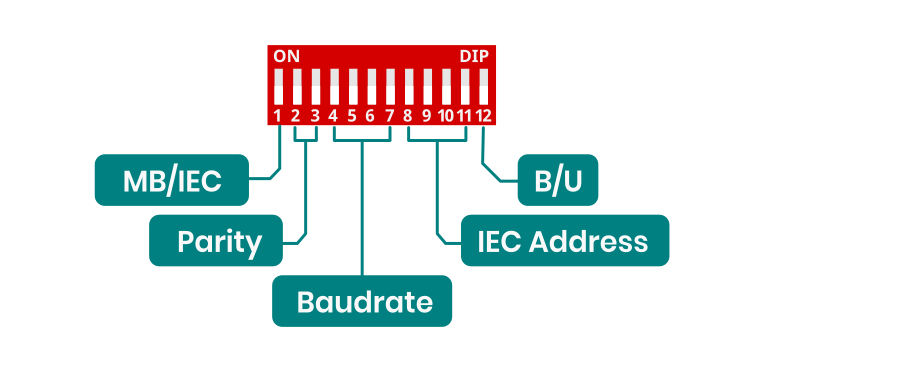](https://docs.atreyo.in/uploads/images/gallery/2025-03/amb-8i-4o-dip-2.png)
##### Parity configuration
Parity configuration for both Modbus and IEC.
| Parity | Function |
| 00
| NONE |
| 01
| ODD
|
| 10
| EVEN
|
| 11
| NONE |
---
##### Baudrate configuration
Baudrate configuration for both Modbus and IEC
| Switch | Baudrate |
| 0000
| 9600 |
| 0001
| 1200 |
| 0010
| 2400 |
| 0011
| 4800 |
| 0100
| 14400 |
| 0101
| 19200 |
| 0110
| 28800 |
| 0111 | 38400 |
| 1000
| 57600 |
| 1001
| 76800 |
| 1010
| 115200 |
| 1011
| 230400 |
| 1100
| 256000 |
| 1101
| 460800 |
| 1110
| 576000 |
| 1111
| 921600 |
---
##### Address configuration for Modbus RTU
| Switch | Value | Modbus Address |
| 00000 | 0
| 1
|
| 00001 | 1
| 2
|
| 00010 | 2
| 3
|
| 00011 | 3
| 4
|
| 00100 | 4
| 5
|
| 00101 | 5
| 6
|
| 00110 | 6
| 7
|
| 00111 | 7
| 10
|
| 01000 | 8
| 20
|
| 01001 | 9
| 30
|
| 01010 | 10
| 40
|
| 01011 | 11
| 50
|
| 01100 | 12
| 60
|
| 01101 | 13
| 70
|
| 01110 | 14
| 80
|
| 01111 | 15
| 90
|
| 10000 | 16
| 100
|
| 10001 | 17
| 110
|
| 10010 | 18
| 120
|
| 10011 | 19
| 130
|
| 10100 | 20
| 140
|
| 10101 | 21
| 150
|
| 10110 | 22
| 160
|
| 10111 | 23
| 170
|
| 11000 | 24
| 180
|
| 11001 | 25
| 190
|
| 11010 | 26
| 200
|
| 11011 | 27
| 210
|
| 11100 | 28
| 220
|
| 11101 | 29
| 230
|
| 11110 | 30
| 240
|
| 11111 | 31
| 250
|
---
##### Address configuration for IEC
| Switch | Value | IEC Address |
| 0000
| 0 | 1
|
| 0001
| 1 | 2
|
| 0010
| 2 | 3
|
| 0011
| 3 | 4
|
| 0100
| 4 | 5
|
| 0101
| 5 | 6
|
| 0110
| 6 | 7
|
| 0111 | 7 | 10
|
| 1000
| 8 | 20
|
| 1001
| 9 | 30
|
| 1010
| 10 | 40
|
| 1011
| 11 | 50
|
| 1100
| 12 | 60
|
| 1101
| 13 | 70
|
| 1110
| 14 | 80
|
| 1111
| 15 | 90
|
---
#### EC60870-5-101 Implementation Guide
##### Protocol Overview
The device implements IEC60870-5-101 protocol with the following key functions:
##### Reading States (Interrogation)
- C\_IC\_NA\_1 (100)
- Reading all inputs and outputs states
- Inputs: 1000-1007
- Outputs: 2000-2003
##### Controlling Outputs
- Function: C\_SC\_NA\_1 (45)
- Purpose: Setting individual output states
- IOA range: 2000-2003
- Values: ON (1) / OFF (0)
#### Command Structure
##### General Interrogation Command
```
Type ID: 100 (C_IC_NA_1)
Qualifier: 20
Cause of Transmission: 6 (Activation)
Common Address: 1
```
##### Single Command (Output Control)
```
Type ID: 45 (C_SC_NA_1)
Cause of Transmission: 6 (Activation)
Common Address: 1
IOA: 2000-2003
Value: 0/1
```
#### SCADA system configuration
##### IEC60870-5-101 Protocol Configuration
- Common Address (ASDU): 1
- Frame format: FT1.2
- Link Layer Address: according to device configuration
##### I/O Points Configuration:
For inputs (8 channels):
- Type: Single Point Information (M\_SP\_NA\_1)
- IOA addresses: 1000-1007
- Direction: Monitoring (read)
For outputs (4 channels):
- Type: Single Command (C\_SC\_NA\_1)
- IOA addresses: 2000-2003
- Direction: Control (write)
Verification:
- Check if input states are correctly read (IOA 1000-1007)
- Confirm control operation for each output (IOA 2000-2003)
- Verify device responds to General Interrogation