Thermolog
Thermolog V3-T is temperature logger dedicated for applications where visual temperature control is needed and it is also necessary to save log to non-volatile memory. Thermolog V3-T has the ability to set the range of the permissible temperature. An alarm is triggered above and below the set temperature. Thermolog V3-T supports the DS12B20 sensor but has optional PT100 sensor support.
Thermolog V3-TH is temperature and humidity logger dedicated to applications where visual temperature control is needed and it is also necessary to save log to non-volatile memory. Thermolog V3-TH has the ability to set the range of the permissible temperature. An alarm is triggered above and below the set temperature.
General information
| Download technical specification Thermolog V3-T |
Technical Specification |
| Download technical specification Thermolog V3-TH | Technical Specification |
Connection
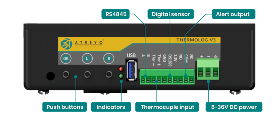
The thermologist on the right has a set of sockets for power and sensor connections. Below is a description of the sockets.
- RS485 is used to connect to a Modbus master, i.e. to an IoT gateway, computer or PLC.
- Push buttons are used to configure Thermolog and change the way the danyuch is displayed
- In place of the digital sensor, depending on the Thermolog version, either a temperature sensor or a temperature and humidity sensor is connected.
- The Alert output is connected to either an optional sound or a sound/visual signaling device. The circuit is in NO/NC form and can control 230V mains voltage up to a maximum of 3A.
- Thermokuple input is adapted to 2-wire PT100 only in the version of Thermolog that supports this sensor
Copy data of Logger
Copying the data of the built-in logger is done with a USB pendrive. To do this, insert a pendrive formatted in FAT32 and restart the device. Thermolog will automatically start copying data to it after detecting the pendrive. The display will show information about the progress of copying.
Once copied, the file on the flash drive will be named Termdump.BIN
To open it you need to use a dedicated PC program - Thermometer.
Firmware update
Thermolog enables firmware updates. For this purpose, you need a flash drive formatted in FAT32. On the flash drive you should copy the firmware to Thermolog. The firmware must be named atgfirmware.bin.
- Insert a pendrive
- Simultaneously press all 3 buttons
- Turn on the power. The display will show Bootloader.
- After a while it will display "press any key" Then press the "L" button
- In a dozen seconds the firmware will update and Thermolog will reboot.
Configuration manual
Thermolog can be configured in two ways. One by using the buttons and the menu that will appear on the display, or by using Modbus and commands from the dedicated Thermometer PC application or any other software with Modbus function. The offered device has default parameters and you should set them according to your requirements.
It is possible to configure:
- the display method
- brightness from 1 to 15 or automatic
- Modbus parameters
- date and time
- sensor calibration
Configuration by buttons
Setting the time on the Thermolog ATL-V3-TH:
- Long press the OK button to enter the time setting mode.
- Use the Left (L) and Right (R) buttons to adjust the time.
- Single press the OK button to switch between setting up minutes, hours, days, and so on.
- This allows you to easily navigate through the different time units and adjust them accordingly.
Attention. Thermolog has the ability to calibrate the clock. In the last menu there is the possibility of acceleration and deceleration. It is best to leave the values as the default, which is 0.
Switching the display mode:
- Press either the Right (R) or Left (L) button.
Setting Brightness of display and Modbus Parameter:
Setting temperature and humidity alert:
- To set the minimum or maximum temperature of the sensor for low or high temperatures, use the OK button along with the Left (L) button.
- Use the Left (L) and Right (R) buttons to adjust the temperature.
- Single press the OK button to switch between low and high temperature.
Using the program on a PC
Thermolog has a dedicated application that makes configuration easy and allows exporting LOG files to Excel format. Thermometer 1.04 does not require installation. It works on computers running Windows 10 and later.
Setting up Thermolog with the Thermometer App
To configure Thermolog, you need to connect a converter to RS485 interface to the USB port of your computer. You can use ADI-501 converter made by Atreyo or any other make. After correctly connecting the RS485 signals between the converter and Thermolog and after connecting to the computer, start the Thermometer application. Then select the port and serial port paramneters. By default, Thermolog is set to Baud rate 9600, Data bits 8, Parity: none, Stop bits: 1, Flow control: none.
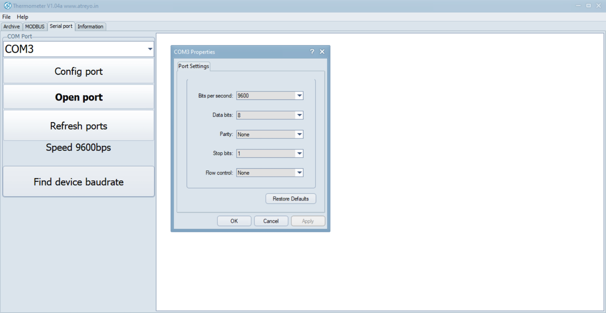
After making the settings, click Open port.
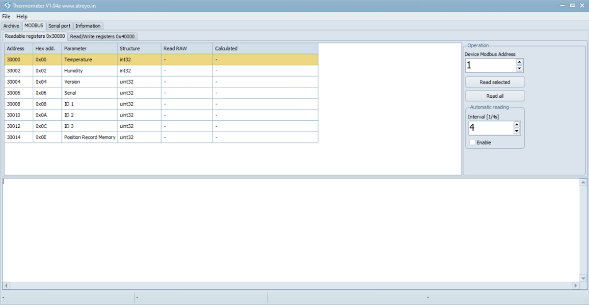
Under Modbus>Redable registers, we have access to the data read from Thermolog.
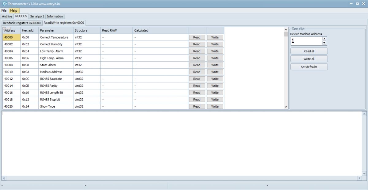
Under Modbus>Read/Write, we also have the option to make changes to the settings.
We can make config of:
- time and date
- temperature alarm range
- humidity alarm range
- make calibration
- set the serial port and Modbus address
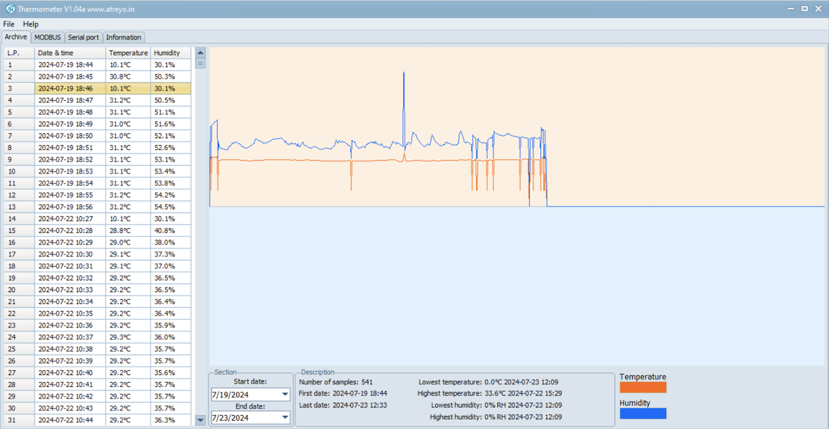
Preview data and export to Excel
To open a preview of data from Thermolog, you need to select File>open in the top menu and open the previously ripped Termdump.BIN file. A graphical representation of the temperature measurements will be shown.
To export data to an Excel file, it is necessary to have Excel installed on your computer.
Protocol Description
Thermolog sends data using the Modbus proto protocol. Below is a description of the protocol.
| Readable registers 0x04 – 30000 | ||||||
| Address | Hex Address | Parameter | Organization | Example Value | Accuracy | Example |
| 30000 | 0x00 | Temperature | int32 | 152 | %0.1f | 15.2 °C |
| 30002 | 0x02 | Humidity | int32 | 457 | %0.1f | 45.7 % |
| 30004 | 0x04 | Version | uint32 | 20201 | %d.%02d.%02d | 2.02.01 |
| 30006 | 0x06 | Serial | uint32 | 7EF8E955 | %08X | 0x7EF8E955 |
| 30008 | 0x08 | ID 1 | uint32 | 05D3FF31 | %08X | 05D3FF313838553443134350 |
| 30010 | 0x0A | ID 2 |
uint32 | 38385534 | %08X | |
| 30012 | 0x0C | ID 3 |
uint32 | 43134350 | %08X | |
| 30014 | 0x0E | Position Record Memory | uint32 | 34897 | %d | 34897 |
| Readable/Writable registers 0x03 – 40000 | |||||||||
|---|---|---|---|---|---|---|---|---|---|
| Address | Hex Address | Parameter | Organization | Example Value | Accuracy | Example | Val. Min | Val.Max | Default |
| 40000 | 0x00 | Correct Temperature | int32 | -12 | %0.1f | -1.2 | -100 | 100 | 0 |
| 40002 | 0x02 | Correct Humidity | int32 | 25 | %0.1f | 2.5 | -100 | 100 | 0 |
| 40004 | 0x04 | Low Temp. Alarm | int32 | -25 | %0.1f | -2.5 | -1200 | 1200 | -1.5 |
| 40006 | 0x06 | High Temp. Alarm | int32 | 20 | %0.1f | 3.0 | -1200 | 1200 | 3.6 |
| 40008 | 0x08 | State Alarm | int32 | 0 | %d | 0 | 0 | 2 | 0 |
| 40010 | 0x0A | Modbus Address | uint32 | 1 | %d | 1 | 1 | 247 | 1 |
| 40012 | 0x0C | RS485 Baudrate | uint32 | 9600 | %d | 9600 | 1200 | 921600 | 9600 |
| 40014 | 0x0E | RS485 Parity | uint32 | 0 | %d | 0 | 0 | 2 | 0 |
| 40016 | 0x10 | RS485 Length Bit | uint32 | 8 | %d | 8 | 8 | 9 | 8 |
| 40018 | 0x12 | RS485 Stop bit | uint32 | 1 | %d | 1 | 0 | 3 | 1 |
| 40020 | 0x14 | Show Type | uint32 | 1 | %d | 1 | 1 | 6 | 1 |
| 40022 | 0x16 | Correct Time | int32 | -13 | %0.1f | -13 | -120 | 120 | -11 |
| 40024 | 0x18 | Light | uint32 | - | %d | - | 0 | 15 | 0 |
| 40026 | 0x1A | Year | uint32 | 1022 | %d | 1022 | 2022 | 2099 | - |
| 40028 | 0x1C | Month | uint32 | 9 | %d | 9 | 1 | 12 | - |
| 40030 | 0x1E | Day | uint32 | 3 | %d | 3 | 1 | 29/30/31 | - |
| 40032 | 0x20 | Hour | uint32 | 15 | %d | 15 | 0 | 23 | - |
| 40034 | 0x22 | Minute | uint32 | 12 | %d | 12 | 0 | 59 | - |
| 40036 | 0x24 | Second | uint32 | 33 | %d | 33 | 0 | 59 | - |
| Correct temperature - each temperature reading is corrected by this value |
|
| Correct Humidity - each humidity reading is corrected for this value |
|
| Low Temp. Alarm - when the temperature is lower than this value, the alarm will be triggered |
|
| High Temp. Alarm - when the temperature is higher than this value, the alarm will be triggered |
|
| State Alarm - there are three alarm states |
|
| ALARM_NONE | 0 |
| ALARMYELLOW | 1 |
| ALARMRED | 2 |
| Show type - determines how the temperature, humidity and time are shown on the LED display |
|
| Correct time - after the end of the day, the time was adjusted by this value |
|
| Light - brightness level of the LED display. For value 0 - the automatic brightness function is enabled. |
|
| Identification Device – ID1+ID2+ID3 - unique value for each device |
|
| Position Record Memory - position in the internal memory organization of the device for archiving the measured temperatures |
|
Communication over Modbus
| Name | Function | Value |
|---|---|---|
| RS485 Baudrate | From 1200 to 921600 | 9600 |
| RS485 Parity | None | 0 |
| Odd | 1 | |
| Even | 2 | |
| RS485 Length Bit | Normal | 8 |
| Extend | 9 | |
| RS485 Stop bit | 0.5 | 0 |
| 0 | 1 | |
| 1.5 | 2 | |
| 2 | 3 |
Safety information
Operating environment
- The device is designed to be installed in clean, dust-free and insect-free places
- Operating temperature: -25 ~ 65°C (-13 ~ 149°F).
- Humidity range is 10% to 95% (non-condensing). Use the device in a dry environment.
- Away from heat sources and direct sunlight.
- It must not be exposed to acid fumes, salts and other chemicals.
- The device must not be used in places where there is a risk of gas explosion.
Use in inappropriate conditions may damage the device or shorten its life.
Electrical and power supply safety
- The device is powered with a voltage in the range of 8-36V. Voltage up to 24V is considered safe. Be especially careful when supplying them with higher voltages.
- Use only approved accessories
- Use the supplied power adapter or a good quality certified power adapter with the correct supply voltage range and sufficient power.
- Only use approved accessories like antenna etc.
Only a person with qualification and appropriate knowledge should install the device.
Malfunctioning and damaged device
- Do not disassemble the device.
- Only qualified personnel must service or repair the device or its accessories.
- If water or other liquid has got into the device, or if it looks mechanically damaged, do not connect the device, but take it to an authorized service center.
What to do and what not to do
- You are solely responsible for the use of the device and any consequences of its use.
- Do not store or use the device in harsh environments such as dust, gases, oils, chemical vapors and damp places.
- Do not throw the device and its accessories. Handle with care.
- The device heats up during operation. Ensure proper ventilation.
- If you need to dispose of your device, check your local regulations for recycling and disposal of electronics.
- Route power, Ethernet, and antenna cables properly so that they cannot be accidentally pulled out.
- The device should be used and kept away from small children.