General information
| Download technical specification | Technical Specification |
Model selection
Different Gateway models are available depending on the periphery availability and type.
| Model |
Cellular Network |
GNSS |
Internal memory |
||||
| GPRS | 3G |
LTR 4G |
5G |
Flash 64MB |
NAND 512MB |
||
| AG-207 | √ | √ | |||||
| AG-207-LT-IN | √ | √ | √ | √ | √ | ||
| AG-207-LT-EU | √ | √ | √ | √ | √ | ||
| AG-207-LT-GL | √ | √ | √ | √ | √ | √ | |
AG-207 is the basic variant of this model. Has a no cellular module.
The AG-207-LT-IN with LTE module. This module is to use in India.
The AG-207-LT-EU is the same as the base model except that it has a cellular module for use India and Europe.
The AG-207-LT-GL is a version with a module certified all over the world.
Hardware informations
The Gateway is made on one PCB, which is fitted to the aluminum housing. The housing is made of a thick, strong aluminum profile with two end plates also made from aluminum. The surface of the housing is finished by anodizing.
At the bottom of the housing there are slots through which DIN rail clamp or any other clamp can be mounted by t-nuts.
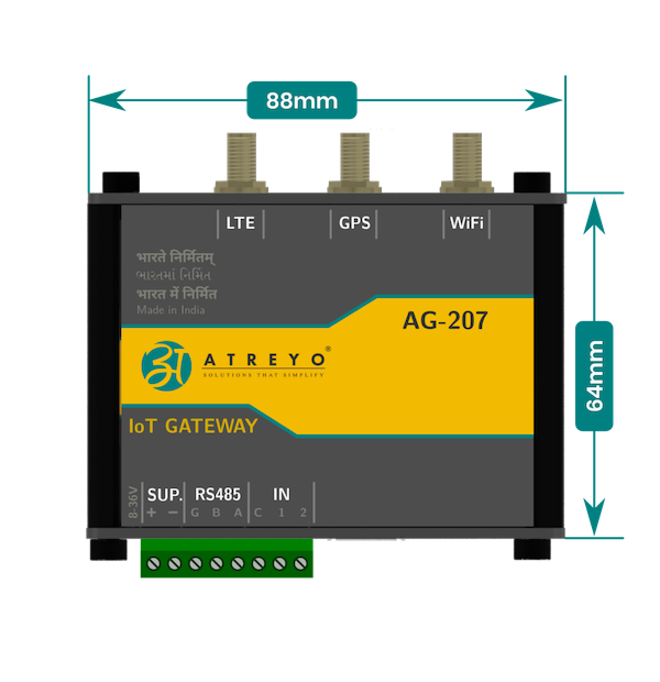
Top view dimensions
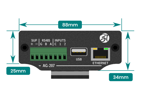
Side view dimensions
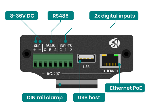
Connectors
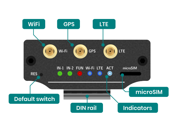
Top view connectors and indicators
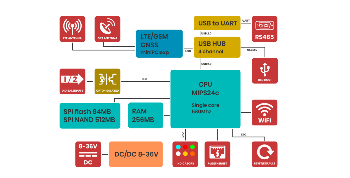
Block diagram
For a better understanding of the operation of the gateway, refer to the block diagram. Non-essential components have been omitted. Developers who program peripherals such as GPIOs, serial etc. will find information about them in the sections dedicated to such peripherals.
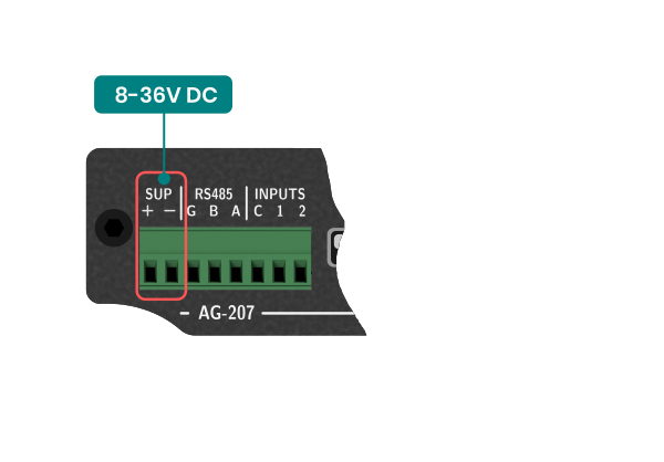
Power supply
The Gateway power supply range is 8-36V DC. First, connect the power supply according to the diagram. The Gateway is protected against reverse power connection. If the polarity is reversed, the Gateway will not start.
PoE
The Gateway can also be powered via PoE in the range of input power supply using unused pairs of wires in the LAN cable. Below is the pinout of the RJ45 socket.
| Pin number |
Function |
Comment |
| 1 |
RX+ | Data |
| 2 |
RX- | Data |
| 3 |
TX+ | Data |
| 4 |
DC+ | Power supply positive |
| 5 |
DC+ | Power supply positive |
| 6 |
TX- | Data |
| 7 |
DC- | Power supply negative |
| 8 |
DC- | Power supply negative |
LTE 4G modem
Generally, the Gateway supports all versions of Quectel MiniPCI express modems. However, you can use a third-party modem, as long as the signal outputs are compatible with those of the Quectel company. For use your LTE module, select model without LTE module installed. You also need to pay attention to the power supply to the LTE module should be 3.3V.
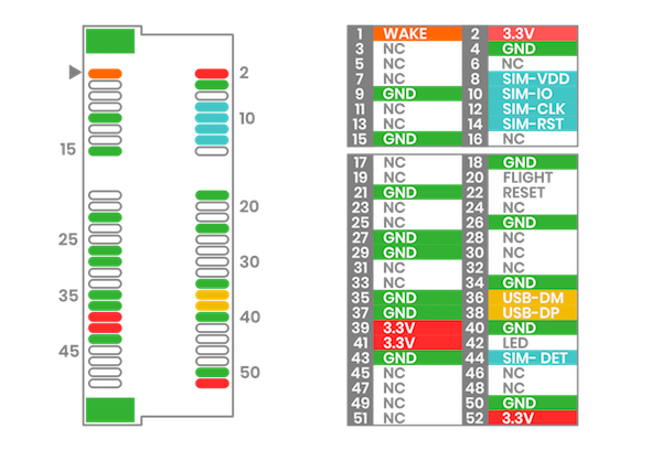
MiniPCI express pinout
Below is the description of the PCI express pinout used in the AG-702. Before installing anything other than the EC200U or EG25, be sure to check the pinout for compatibility. The LTE model is connected via a USB data bus.
GNSS
Device has wboded LTE modem along with GNSS function. In order to receive the GNSS signal, an antenna is required. There are two types of GNSS antennas: active gnss antenna and passive gnss antenna. The AG-702 supports both types of antennas, but in order for the active antenna to work properly, it is necessary to start powering the active antenna. To do this, you need to go to System > Custom Commands and select the command Turn GPS antenna to active mode.
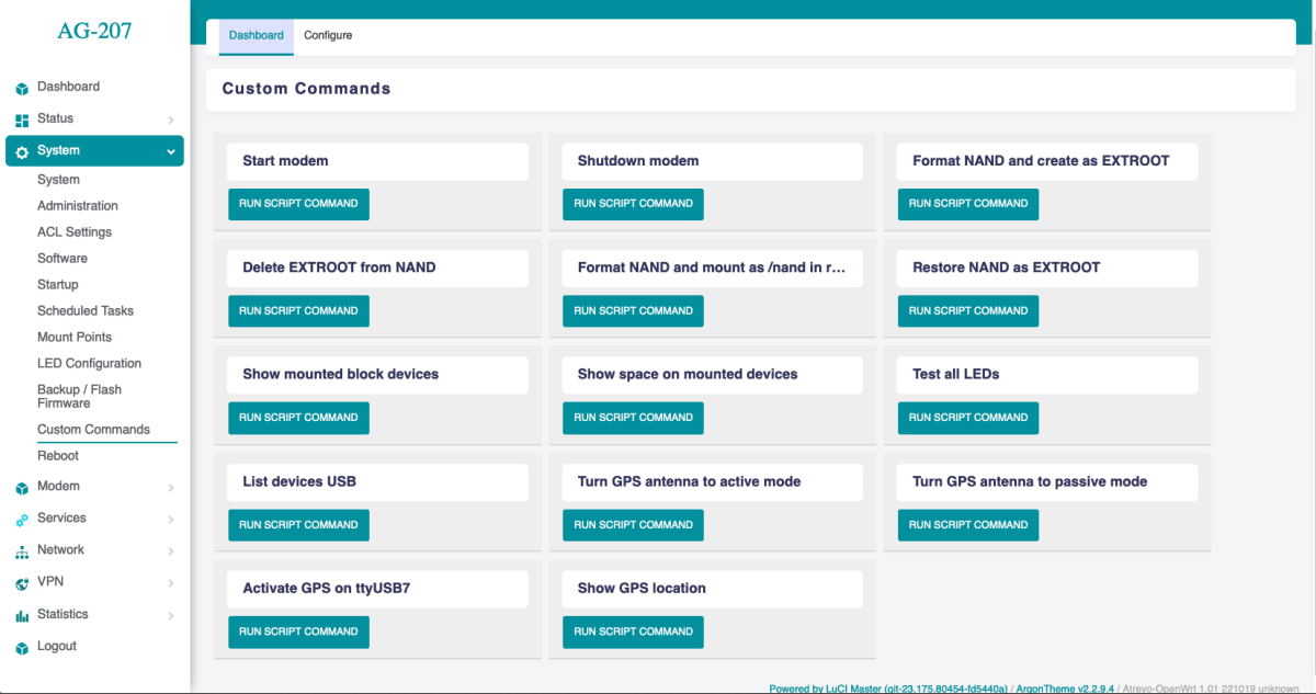
Also on this page, you can test whether the GNSS is working properly. To do so, you need to click Activate GPS on ttyUSB7 and then Show GPS location.
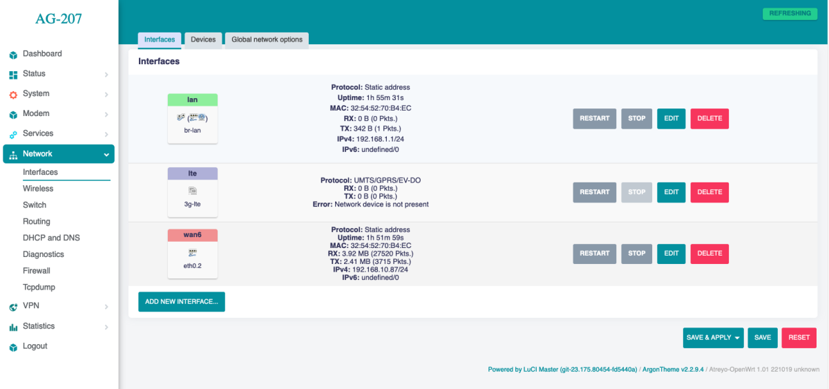
Ethernet
The gateway has one RJ45 ethernet ports with LED indicators. The speed of each is 100Mbps. Ethernet, IP and other settings are set on the Network > Interfaces page.
The default IP of ethernet is:
192.168.1.60
WiFi
The gateway has WiFi 2.4Ghz. By default, the WiFi is set as a hotspot and shares internet from Ethernet and from LTE via WiFi.
WiFi is used for remote configuration of the device. It does not have a long range, so it may not fully meet some requirements.
Serial Interface
The Gateway has one RS485.
RS485
The baudrate range for RS485 port (/dev/ttyUSB0) is 600 bps to 460800 bps. Note that with a longer cable, the maximum speed may drop. It is recommended to use special cables designed for RS485. The port is protected by high-power TVS diodes against electrical surges.
Digital Inputs
The Gateway has two digital inputs and one digital output.
Digital inputs
The digital inputs are completely independent optically isolated inputs that accept an input signal level of up to 30V DC. They have no common minus. They can be connected either with a common plus or minus. Can be controlled with open collector. They require to be powered. The range of the signal considered as a logical 1 is from 3.5V to the maximum input voltage.