
Modbus and Serial Configuration
1. Modbus and Serial Configuration
The Gateway has a very advanced Modbus application with a convenient graphical interface. Below are the capabilities of the application:
1.1 Modbus fundamentals
Modbus is an industrial communication protocol used to exchange data between a client/master and one or more server/slave devices. The client starts the request and the server returns the requested data. This guide only covers the Modbus TCP and Modbus RTU functions used by this Modbus Master application.
502 is the standard Modbus TCP port.
Modbus RTU
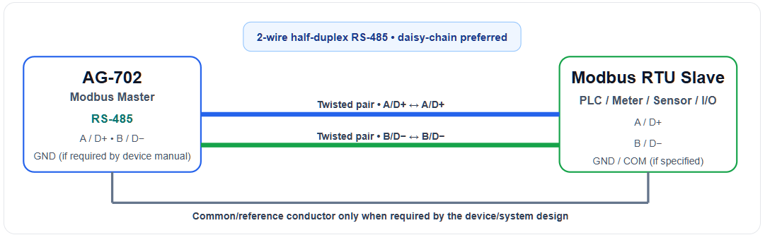
Uses a serial communication link such as RS-485. Configure the serial port and the serial communication settings to match the slave.
Always start with the slave manufacturer's Modbus map. It tells you the communication settings, slave/unit address, function code, register/coil address, quantity and data format required for that device.
1.2 Select the Communication Method
Do not mix the settings. Modbus TCP uses an IP connection; Modbus RTU uses serial communication parameters.
1.3 Wiring & physical connections
Use the examples below as connection patterns. Exact connector names and polarity markings must always be checked against the connected device's own hardware manual.
Example A — Modbus RTU over RS-485 (2-wire)
Example B — Modbus RTU over RS-232 (point-to-point)
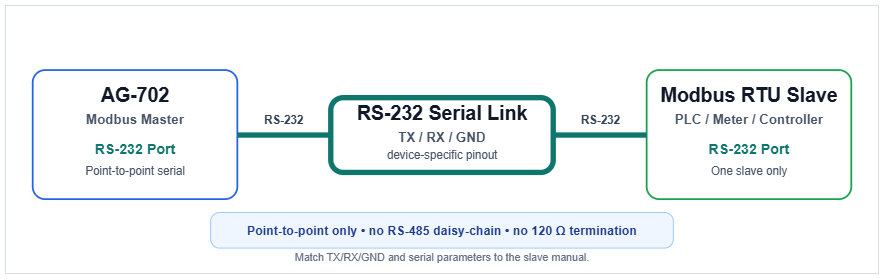
Important: RS-232 is a point-to-point serial interface. Do not use an RS-485 bus wiring model on an RS-232 port. Match TX/RX/GND and the slave's serial parameters exactly as specified by the slave hardware manual.
Example C — Modbus TCP over Ethernet
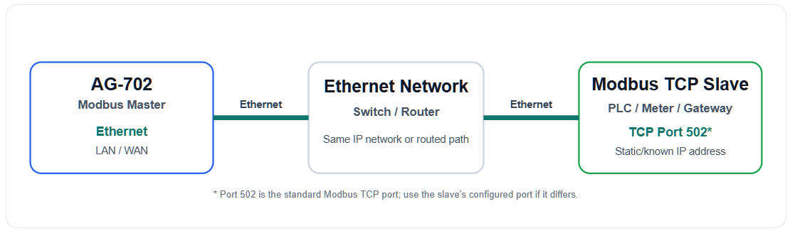
502 is the standard Modbus TCP port.
2. Modbus Deployment Scenarios
These diagrams show how the AG-702 can collect data from multiple RS-485 Modbus RTU slaves and multiple Modbus TCP/IP slave devices.
2.1 AG-702 Mixed TCP/IP & RS-485 Deployment
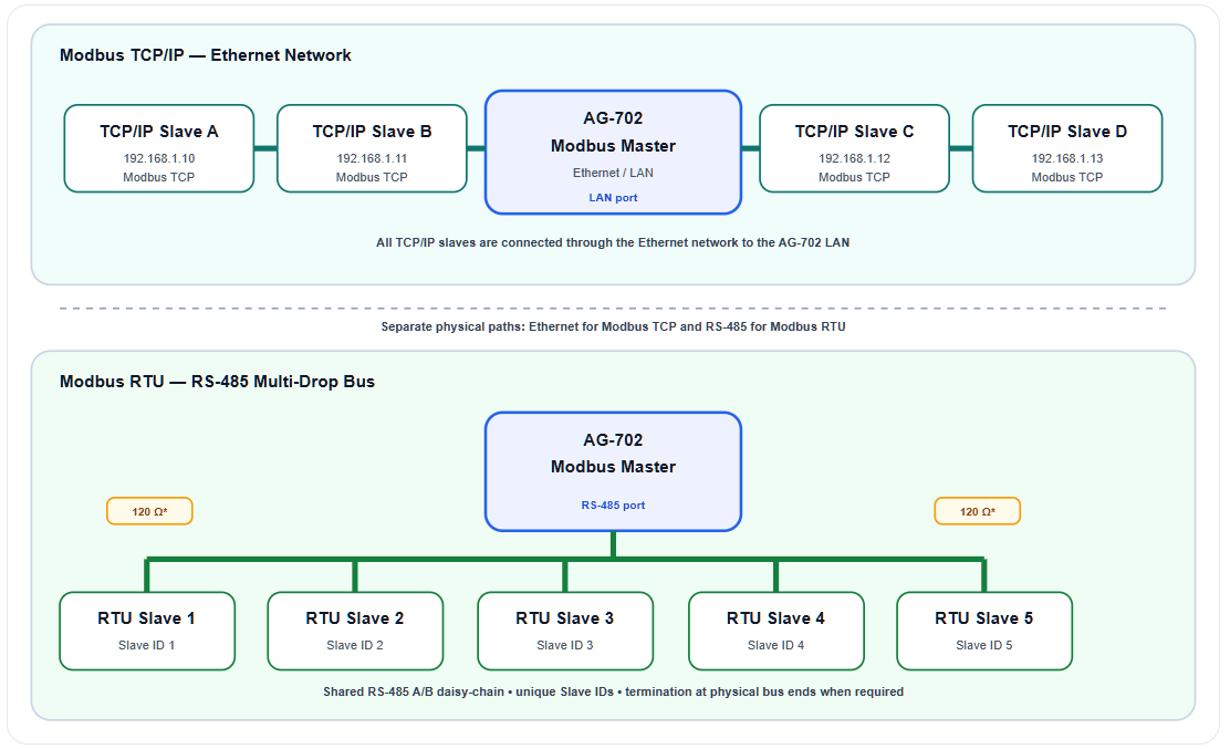
In this example the AG-702 is the central Modbus Master. Five RTU slaves share one RS-485 daisy-chain connected directly to the AG-702 RS-485 port: three slaves are shown on the left and two on the right. Four separate TCP/IP slaves connect through the Ethernet network on the AG-702 LAN side.
Important: RTU slaves are connected to the AG-702 RS-485 port. TCP/IP slaves are connected through the AG-702 Ethernet/LAN port. These are two separate physical communication paths.
2.2 RS-485 Daisy-Chain Wiring — Multi-Slave Field Example
A single AG-702 RS-485 port can serve multiple Modbus RTU slave devices on one shared two-wire bus. Connect A (D+) to A (D+) and B (D−) to B (D−) throughout the chain, assign a unique Slave ID to every device, and install a 120 Ω termination resistor between A and B only at the two physical ends of the bus.
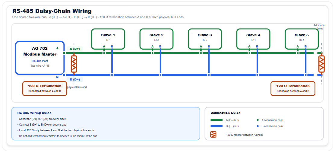
Important: RS-485 is a shared two-wire bus. Keep the topology physically ordered as a daisy-chain, keep drop cables short, connect A to A and B to B consistently, and place 120 Ω termination resistors only at the two physical ends of the bus.
A detailed guide to Modbus configuration is available here.