Configuration manual
Basic information
AMB-8I-4O is an I/O expander operating over Modbus RTU and IEC60870-5-101 protocol. The first DIP switch is used to switch between Modbus RTU and IEC modes. If it is in position 0, then the AMB is operating in Modbus RTU mode. If it is in position 1, then it works in the IEC protocol. As the two protocols have different functions, the DIP switch is also different. In IEC mode, the last DIP switch is used to change the operating mode from balanced/unbalanced. To save the DIP switch settings in the internal memory, the SAVE button must be pressed.
Configuration
DIP switch configuration
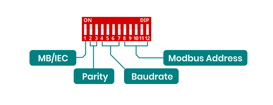
This is DIP switch functions diagram for Modbus RTU configuration. For enable Modbus RTU protocol 1 switch should be in OFF position.
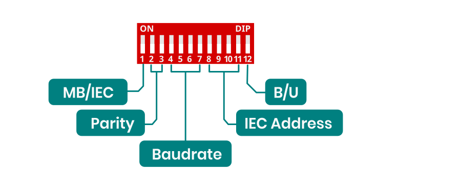
This is DIP switch function diagram for IEC protocol. For enable IEC protocol 1 switch should be in ON position.
Parity configuration
Parity configuration for both Modbus and IEC.
| Parity | Function |
| 00 |
NONE |
| 01 |
ODD |
| 10 |
EVEN |
| 11 |
NONE |
Baudrate configuration
Baudrate configuration for both Modbus and IEC
-
Switch Baudrate 0000 9600 0001 1200 0010 2400 0011 4800 0100 14400 0101 19200 0110 28800 0111 38400 1000 57600 1001 76800 1010 115200 1011 230400 1100 256000 1101 460800 1110 576000 1111 921600
Address configuration for Modbus RTU
Switch Value Modbus Address 00000 0 1 00001 1 2 00010 2 3 00011 3 4 00100 4 5 00101 5 6 00110 6 7 00111 7 10 01000 8 20 01001 9 30 01010 10 40 01011 11 50 01100 12 60 01101 13 70 01110 14 80 01111 15 90 10000 16 100 10001 17 110 10010 18 120 10011 19 130 10100 20 140 10101 21 150 10110 22 160 10111 23 170 11000 24 180 11001 25 190 11010 26 200 11011 27 210 11100 28 220 11101 29 230 11110 30 240 11111 31 250
Address configuration for IEC
| Switch | Value | IEC Address |
| 0000 |
0 | 1 |
| 0001 |
1 | 2 |
| 0010 |
2 | 3 |
| 0011 |
3 | 4 |
| 0100 |
4 | 5 |
| 0101 |
5 | 6 |
| 0110 |
6 | 7 |
| 0111 | 7 | 10 |
| 1000 |
8 | 20 |
| 1001 |
9 | 30 |
| 1010 |
10 | 40 |
| 1011 |
11 | 50 |
| 1100 |
12 | 60 |
| 1101 |
13 | 70 |
| 1110 |
14 | 80 |
| 1111 |
15 | 90 |
EC60870-5-101 Implementation Guide
Protocol Overview
The device implements IEC60870-5-101 protocol with the following key functions:
Reading States (Interrogation)
- C_IC_NA_1 (100)
- Reading all inputs and outputs states
- Inputs: 1000-1007
- Outputs: 2000-2003
Controlling Outputs
- Function: C_SC_NA_1 (45)
- Purpose: Setting individual output states
- IOA range: 2000-2003
- Values: ON (1) / OFF (0)
Command Structure
General Interrogation Command
Type ID: 100 (C_IC_NA_1)
Qualifier: 20
Cause of Transmission: 6 (Activation)
Common Address: 1
Single Command (Output Control)
Type ID: 45 (C_SC_NA_1)
Cause of Transmission: 6 (Activation)
Common Address: 1
IOA: 2000-2003
Value: 0/1
SCADA system configuration
IEC60870-5-101 Protocol Configuration
- Common Address (ASDU): 1
- Frame format: FT1.2
- Link Layer Address: according to device configuration
I/O Points Configuration:
For inputs (8 channels):
- Type: Single Point Information (M_SP_NA_1)
- IOA addresses: 1000-1007
- Direction: Monitoring (read)
For outputs (4 channels):
- Type: Single Command (C_SC_NA_1)
- IOA addresses: 2000-2003
- Direction: Control (write)
Verification:
- Check if input states are correctly read (IOA 1000-1007)
- Confirm control operation for each output (IOA 2000-2003)
- Verify device responds to General Interrogation