Configuration Modbus
DIP switch configuration
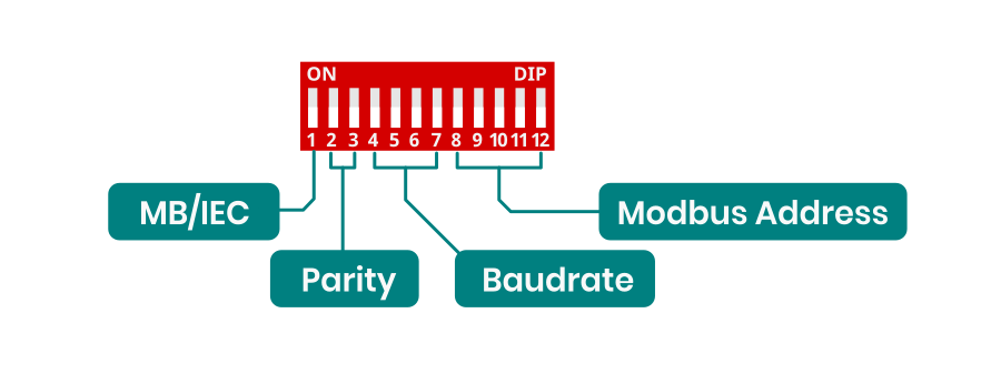
This is DIP switch functions diagram for Modbus RTU configuration. For enable Modbus RTU protocol 1 switch should be in OFF position.
-
Baudrate configuration
Baudrate configuration for both Modbus and IEC
-
Switch Baudrate 0000 9600 0001 1200 0010 2400 0011 4800 0100 14400 0101 19200 0110 28800 0111 38400 1000 57600 1001 76800 1010 115200 1011 230400 1100 256000 1101 460800 1110 576000 1111 921600
Address configuration for Modbus RTU
Switch Value Modbus Address 00000 0 1 00001 1 2 00010 2 3 00011 3 4 00100 4 5 00101 5 6 00110 6 7 00111 7 10 01000 8 20 01001 9 30 01010 10 40 01011 11 50 01100 12 60 01101 13 70 01110 14 80 01111 15 90 10000 16 100 10001 17 110 10010 18 120 10011 19 130 10100 20 140 10101 21 150 10110 22 160 10111 23 170 11000 24 180 11001 25 190 11010 26 200 11011 27 210 11100 28 220 11101 29 230 11110 30 240 11111 31 250 Address 1–247 → valid slave IDs for individual devices
Address 0 → reserved for broadcast messages; all slaves receive it but no one replies
Addresses 248–255 → reserved/unassigned (not permitted for standard device addressing) -

