
Modbus Master basic info
1.1 Communication Parameters
| Parameter | RTU | TCP | Where you get it |
|---|---|---|---|
| Slave / Unit ID | Required | Device dependent; keep the device's required unit identifier | Slave manual / configuration |
| IP address | Not used | Required | Network configuration |
| TCP port | Not used | Usually 502 | Slave manual / network configuration |
| Serial port | Required | Not used | AG-702 device interface |
| Baudrate | Required | Not used | Slave communication settings |
| Data bits | Required | Not used | Slave communication settings |
| Parity | Required | Not used | Slave communication settings |
| Stop bits | Required | Not used | Slave communication settings |
| Function code | Required per query | Required per query | Slave Modbus map |
| Start address | Required per query | Required per query | Slave Modbus map |
| Quantity | Required per query | Required per query | Slave Modbus map |
| Datatype / byte order | Required for decoded values | Required for decoded values | Slave Modbus map |
1.2 Modbus Function Codes Used by This Application
| Function code | Standard meaning | How it appears in this UI |
|---|---|---|
01 |
Read Coils | 01 — Read/Write Coils |
02 |
Read Discrete Inputs | 02 — Read Discrete Inputs |
03 |
Read Holding Registers | 03 — Read/Write Holding Register |
04 |
Read Input Registers | 04 — Read Input Register |
The application UI exposes these four query options. The Modbus specification defines 01/02/03/04 as read operations; write functions use other standard function codes. This guide does not add write configuration that the current UI does not expose.
2. Supported Hardware & Devices
This section separates OpenWrt gateways that can host Modbus software from field devices that can act as Modbus slaves and provide data to the gateway.
2.1 OpenWrt Modbus Gateways
The following Atreyo gateway models have public product information explicitly listing OpenWrt and Modbus support. This is a platform capability table; the exact Modbus Master UI in the supported-device section is verified in this guide only on AG-702.
| Gateway | OpenWrt | Modbus capability | Interfaces | Application status |
|---|---|---|---|---|
| AG-702 | OpenWrt 23.05 | TCP slave, TCP master, RTU master, RTU gateway | 2× Ethernet, RS-485, RS-232 | Verified in this guide |
| AG-221 | OpenWrt 23.05 | TCP slave, TCP master, RTU master, RTU gateway | 2× Ethernet, RS-485 | Validate firmware/package |
| AG-207 | OpenWrt 23.05 | TCP slave, TCP master, RTU master, RTU gateway | 1x Ethernet, 1x isolated RS-485 | Validate firmware/package |
| AG-205 | OpenWrt 23.05 | TCP slave, TCP master, RTU master, RTU gateway | 2× Ethernet, Wi-Fi | Validate firmware/package |
| AG-707 | OpenWrt 23.05 | TCP slave, TCP master, RTU master, RTU gateway | 2× Ethernet, 2× isolated RS-485 | Validate firmware/package |
| AG-743 | OpenWrt | TCP slave, TCP master, RTU master, RTU gateway | 4× Ethernet, RS-485 | Validate firmware/package |
| AG-104 | OpenWrt | TCP slave, TCP master, RTU master, RTU gateway | 1x Ethernet, 1x isolated RS-485 | Validate firmware/package |
2.2 Atreyo Products That Can Act as Modbus RTU Slaves
These products can be placed on the Gateway RS-485 bus as field devices. The Gateway acts as Modbus Master and reads the data exposed by each device according to its own Modbus documentation.
| Product | Interface | Role / protocol | Example data for AG-702 |
|---|---|---|---|
| Thermolog V3-T | RS-485 | Modbus RTU slave | Temperature registers |
| Thermolog V3-TH | RS-485 | Modbus RTU slave | Temperature / humidity registers |
| AMB-4I-4O | RS-485 | Modbus RTU I/O module; all Modbus masters | Input status and relay control |
| AMB-8I-4O | RS-485 | Modbus RTU / IEC-60870-5-101 | Input status and relay control |
| AMB-12I-4O | RS-485 | Modbus RTU I/O module; all Modbus masters | Input status and relay control |
| AMB-8I-AC | RS-485 | Modbus RTU I/O module; all Modbus masters | Input status |
| AMB-16I-AC | RS-485 | Modbus RTU I/O module; all Modbus masters | Input status |
| ADI-524 | RS-485 | Modbus RTU | Input status |
Physical connection: These RTU slave devices connect to the Gateway RS-485 port and share the RS-485 bus. They do not connect to the Gateway Ethernet/TCP port.
3. Deployment Scenarios
These diagrams show how the AG-702 can collect data from multiple RS-485 Modbus RTU slaves and multiple Modbus TCP/IP slave devices.
3.1 AG-702 Mixed TCP/IP & RS-485 Deployment
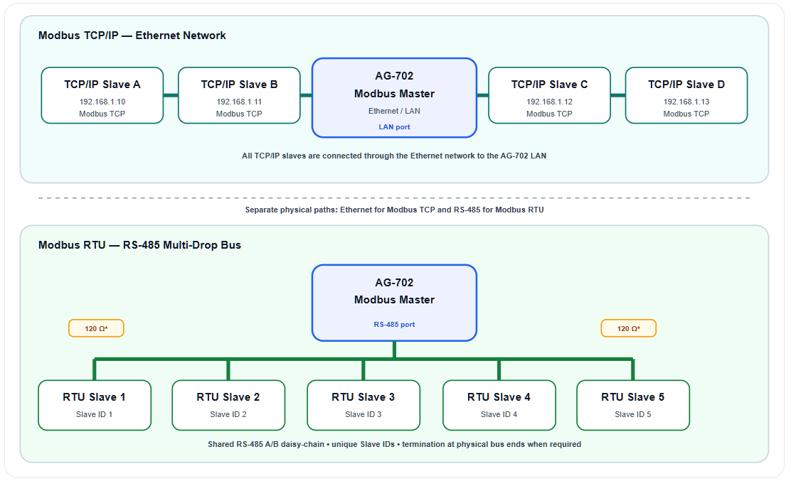
In this example the AG-702 is the central Modbus Master. Five RTU slaves share one RS-485 daisy-chain connected directly to the AG-702 RS-485 port: three slaves are shown on the left and two on the right. Four separate TCP/IP slaves connect through the Ethernet network on the AG-702 LAN side.
| RS-485 side — five RTU slaves |
|
| Ethernet side — four TCP/IP slaves |
|
| Device group | Physical connection | Protocol | Addressing |
|---|---|---|---|
| RTU Slave 1–5 | AG-702 RS-485 → shared A/B bus | Modbus RTU | Slave IDs 1–5 |
| TCP/IP Slave A–D | AG-702 LAN → Ethernet network → slave | Modbus TCP | IP address + device/unit identifier as required |
Important: RTU slaves are connected to the AG-702 RS-485 port. TCP/IP slaves are connected through the AG-702 Ethernet/LAN port. These are two separate physical communication paths.
3.2 RS-485 Daisy-Chain Wiring — Multi-Slave Field Example
A single AG-702 RS-485 port can serve multiple Modbus RTU slave devices on one shared two-wire bus. Connect A (D+) to A (D+) and B (D−) to B (D−) throughout the chain, assign a unique Slave ID to every device, and install a 120 Ω termination resistor between A and B only at the two physical ends of the bus.
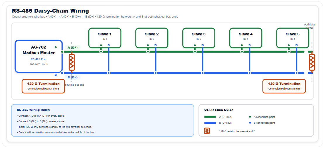
Important: RS-485 is a shared two-wire bus. Keep the topology physically ordered as a daisy-chain, keep drop cables short, connect A to A and B to B consistently, and place 120 Ω termination resistors only at the two physical ends of the bus.