Configuration Manual
Please read carefully before starting. Also read the product safety information.
Wiring and connection
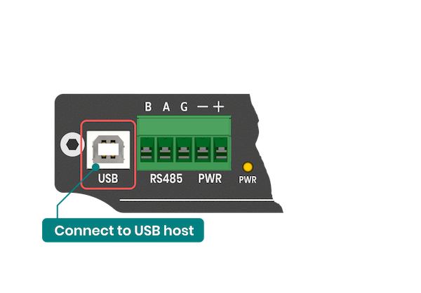
The ADI-524 can be powered from a DC power supply in the range of 8-36V. Also, it can be powered from the USB port of a computer or IoT gateway. Both power sources can be connected simultaneously without fear of damage.
In order to connect sensors with a 4-20mA output, it is necessary to provide them power in the loop. Here are some possible connection methods. Either the built-in isolated 24V power supply can be used or an external current loop power supply can be used.
All current inputs marked as - on the housing are connected together. The isolated 24V, on the other hand, has no galvanic connection to any of the inputs.
Connection Diagrams
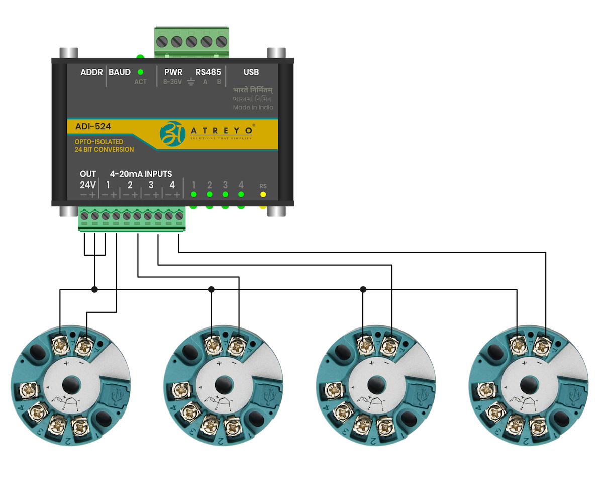
Built-in 24V
Connection of four RTD converters using the built-in 24V power supply.
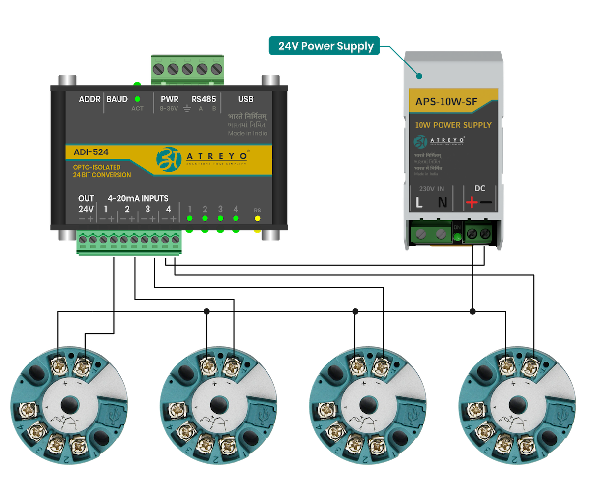
External 24 V
Connection of four RTD converters using the external 24V power supply.
Modbus configuration
It is necessary to set the serial port parameters and the Modbus address using the DIP switch before powering on the device. (reference table for both are given below)
Make sure to reboot/restart device irrespective of any change in DIP switch to be reflected in hardware
MODBUS Serial Port Parameter
| Parameter | Option/range |
| Baudrate | 9600 – 115200 configurable |
| ata bit | 8 |
| Parity | None |
| Stop bit | 1 |
MODBUS Baudrate Configuration
User can set the baud rate using 2 Bit DIP switch. This allows to set baud rate between 9600bps to 115200bps as shown below table.
| Baudrate |
SW1 |
SW2 |
| 9600 | OFF |
OFF |
| 19200 | ON |
OFF |
| 38400 | OFF | ON |
| 115200 | ON | ON |
After setting up the switch, it is necessary to restart the ADI by disconnecting the power supply and, if using USB power, to disconnect it.
MODBUS Address configuration
User can set the slave ID address using 4 Bit DIP switch. This allow 0 to 15 different IDs to be set. The number below the switches are added together and the result will be identifier of the device slave ID.
| Slave ID | SW3 | SW4 | SW5 | SW6 |
| 1 |
OFF |
OFF | OFF | OFF |
| 1 |
ON |
OFF | OFF | OFF |
| 2 |
OFF | ON | OFF |
OFF |
| 3 |
ON |
ON |
OFF | OFF |
| 4 |
OFF |
OFF | ON |
OFF |
| 5 |
ON |
OFF | ON |
OFF |
| 6 |
OFF | ON |
ON |
OFF |
| 7 |
ON |
ON |
ON |
OFF |
| 8 |
OFF | OFF | OFF | ON |
| 9 |
ON |
OFF | OFF | ON |
| 10 |
OFF | ON |
OFF | ON |
| 11 |
ON |
ON |
OFF | ON |
| 12 |
OFF | OFF | ON |
ON |
| 13 |
ON |
OFF | ON |
ON |
| 14 |
OFF | ON |
ON |
ON |
| 15 |
ON |
ON |
ON |
ON |