Configuration manual
Connect the correct power supply. You can choose the right power supply in the power supply section.
Then connect the LAN cable to the gateway to the router. It is important that the IP address is in the range of 192.168.10.xxx.
To enter internal website of Gateway make proper LAN connection and in browser address tab enter Gateway IP. The default IP is:
192.168.10.50.
User name: atreyo
password: atreyo.

- A, B, C – for digital outputs
- Req – request modbus device
- Req. dev. – request modbus device
- Devices – RTU configurations devices
- Serial – configuration serial communication
- Permission – permission configuration for mobile numbers
- Guard – for monitoring communication and activity
- GSM – GSM, LTE, GPRS configuration like APN, password etc.
- Server – server configuration
- Ethernet – Ethernet configuration
- Update – upload firmware and remote update configuration
- Options – for date, time, location, default etc.
- Config – backup, restore and remote configuration.
- Access – access configurations for internal website
- Info – main page with information about model, firmware version etc.
Ethernet
The LAN interface use standard RJ45 8 pin connector with LED indicators. The connector support PoE class A, with power supply range 8-36V DC. If we use screw terminal power connector to power the device the LAN line is protected against back voltage from device. The device is protected from reverse power polarity. If unknowingly it is reverse connected, the Gateway will not work, but will not be damaged. Follow the diagram of connection.
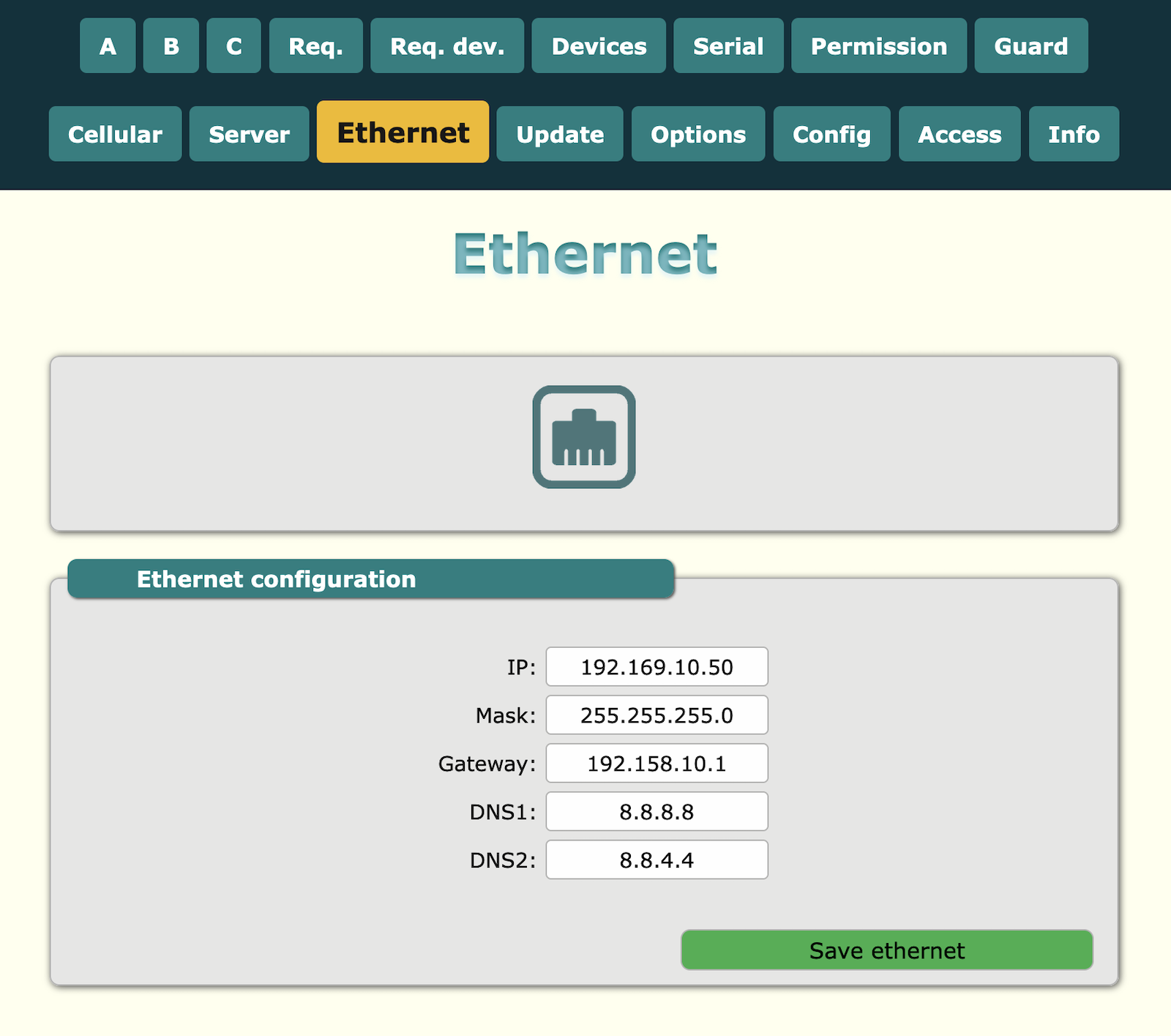
Configuration of Ethernet
Ethernet configuration for LAN. Default value is:
IP = 192.168.10.50
Mask = 255.255.255.0
Gateway = 192.168.10.1
DNS1 = 8.8.8.8
DNS2 = 8.8.4.4
LTE modem
Gateway has inbuilt LTE modem with support of LTE and GPRS.
SIM card
The device support microSIM with voltage 1.8 and 3V. The card holder is push-in/push-out type. Ensure inserting SIM card in proper direction according to the illustration.
Antenna
The device has two female SMA connector for LTE/GSM antenna and for GPS antenna. For proper working it is necessary to connect LTE + GSM band antenna and proper GPS antenna. Antenna line is 50Ω type. Do not switch on device without antenna connected. For better connectivity in remote area it is necessary to use high gain antenna and place it outside of electrical panel box.
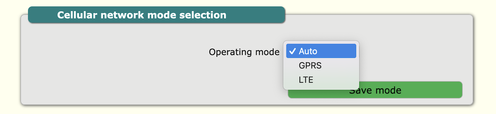
Cellular network configuration
Configuration for mode of connection. Default is auto. But if you are using a SIM card that has only GPRS available, set the connection type to GPRS. If it has only LTE then select LTE and if it has both then you can leave it at auto.
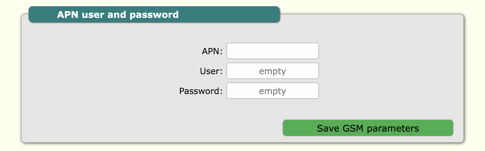
 GSM configuration include: APN, user and password.
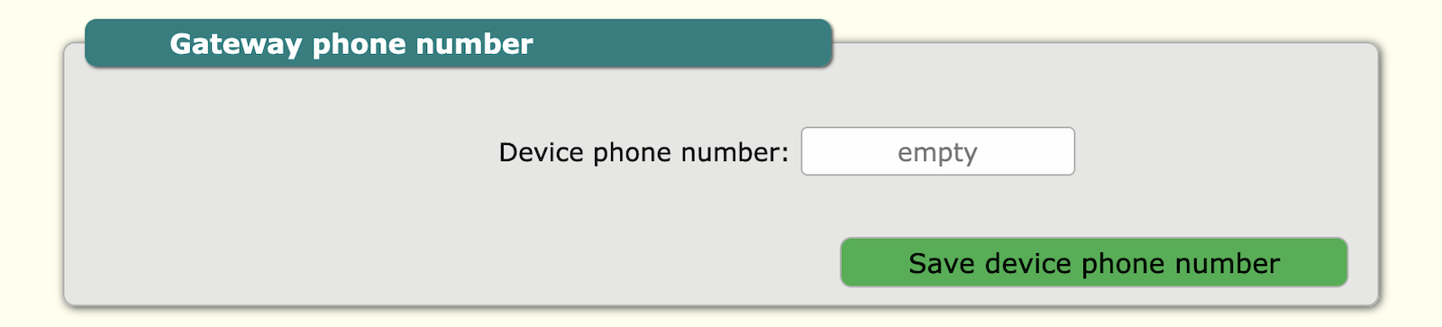
Gateway phone number is Gateway SIM card phone number. It is not necessary to provide this, but in future this information is accessible by TCP/IP and for maintenance is good practice to add this number.
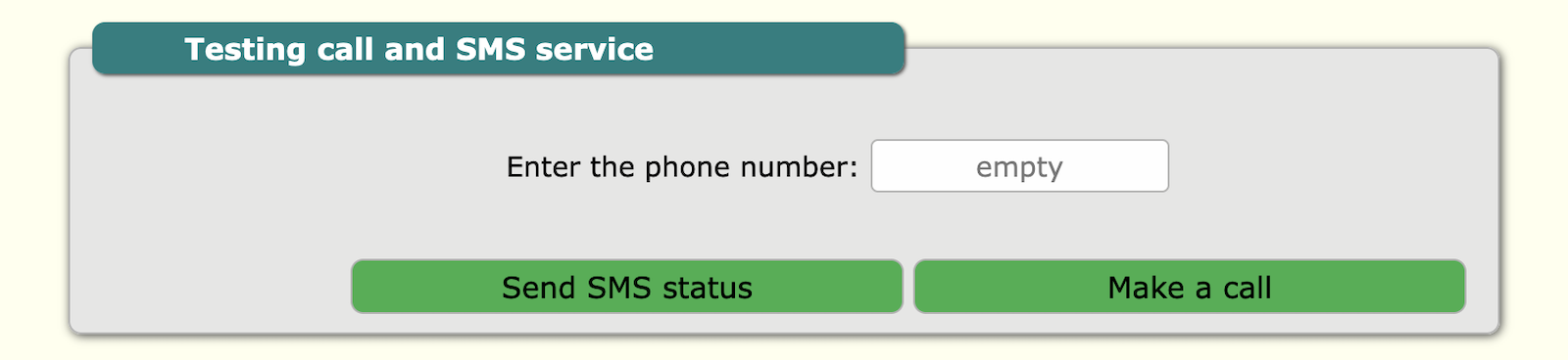
Cellular network testing is for testing of SIM card and network. You can add your number and Gateway will call or send SMS to this number. For this purpose, call and SMS support must be enabled with the mobile operator.
GNSS
The gateway has a built-in GNSS module which is used as a source of accurate time and location. GNSS settings are known in the LTE modem settings tab
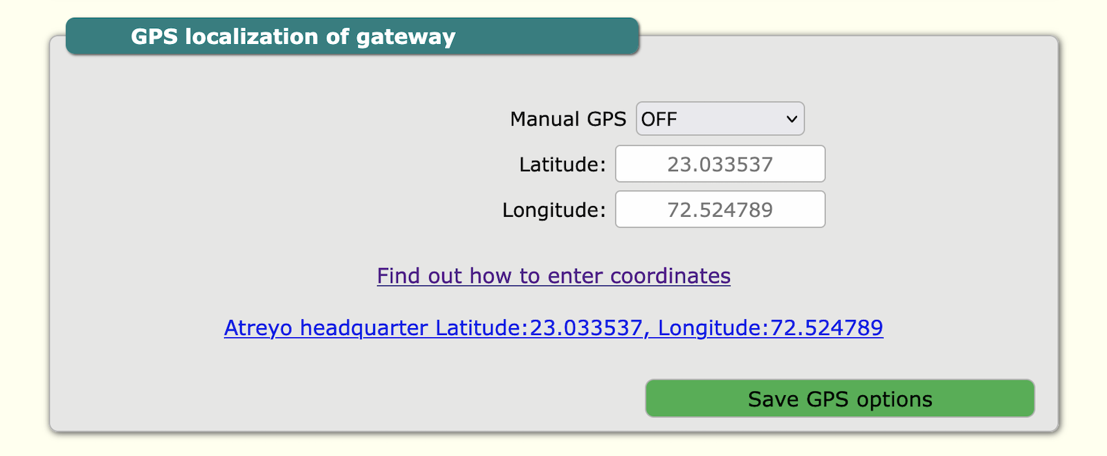
Manual GPS
The location is needed for the solar timer system. In some situations, the gateway is placed in such a location that it does not catch the GNSS signal, and for this purpose there is a manual GPS option. To use this option, you need to enter the longitude and latitude manually.
Powering the active GNSS antenna
The gateway has the ability to accommodate both passive and active GNSS antennas. The supply voltage of the active antenna is 3.3V. To enable the power supply, select Antenna power supply ON.
RS485 – Modbus
The device has opto-isolated RS485 interface with support of Modbus RTU. It is dedicated to energy meter, voltage meter and any Modbus device like PLC which support Modbus RTU protocol. The device supports multiple Modbus devices with separate address range. It is possible to directly send and receive any value of register from server. Please follow proper connection of A and B signals from device to A and B signals in power meter. If the polarity is reversed there will be no data transmission. All modbus configuration like baud-rate, parity, address available in internal website.
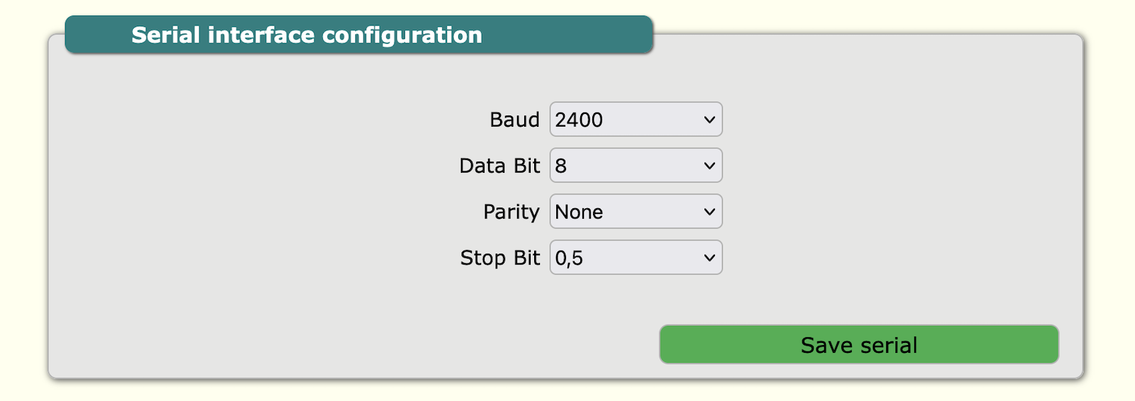
Serial Configuration
In this section are RS485 parameter configuration: baud rate, data bit, parity and stop bit.
| Parameter |
Option/range |
| Baud-rate | 2400 to 460800 |
| Data bit | 8, 9 |
| Parity | None, Even, Odd |
| Stop bit | 1, 1.5, 2 |
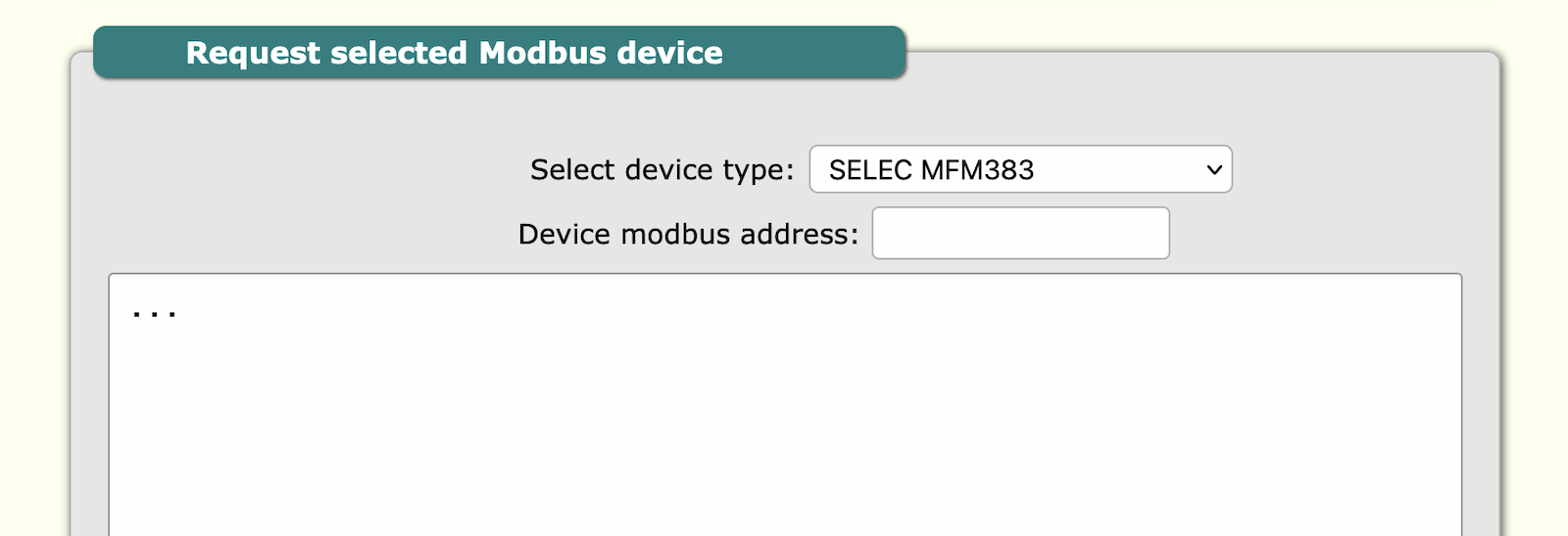
Req. dev. – Request device log
In this section is visible log of modbus devices. In this tab is optional feature to make support for Selec® company meter without necessity to set modbus device details. In window the reply from Selec® device will be visible. Now 2 models of meters are supported MFM383 and EM2M.
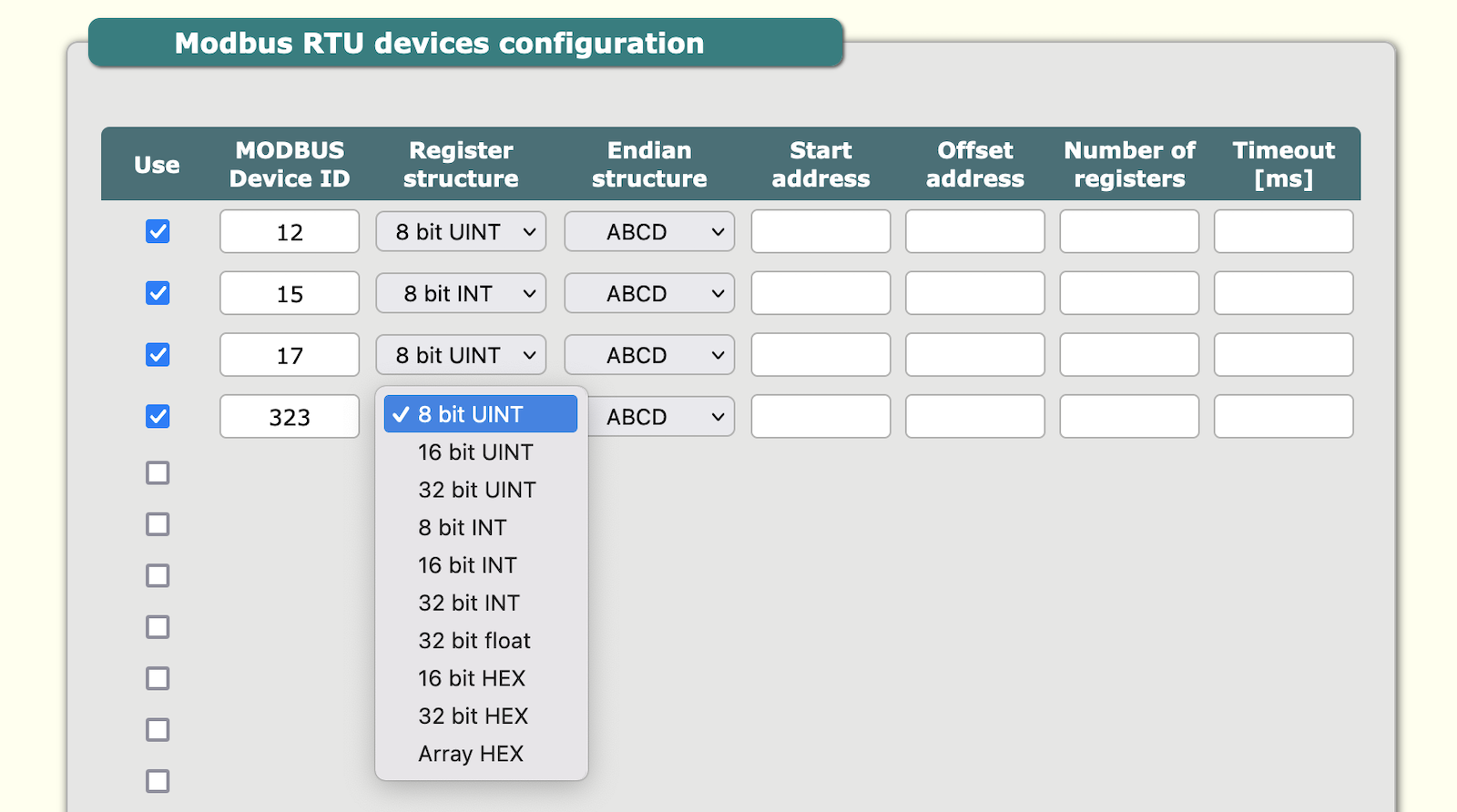
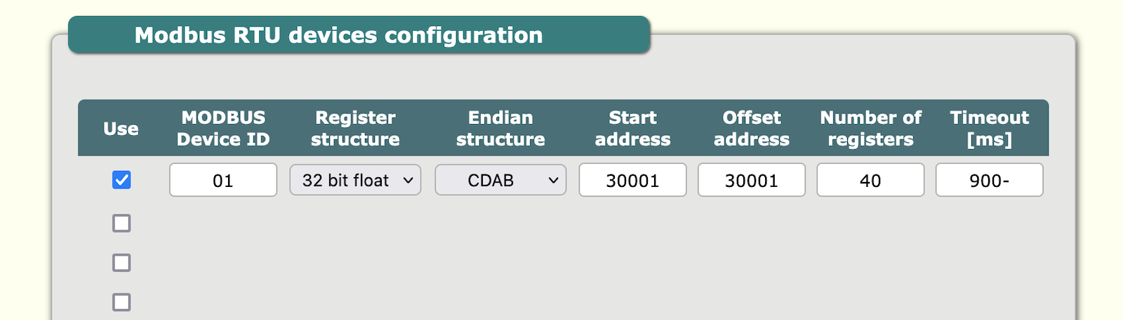
Devices – Modbus devices
Modbus devices configuration of modbus devices connected to Gateway. Configuration of: device ID, register, endian, start address, offset address, registers, timeout. It can add multiple devices up to maximum 16.
| Sn | Parameter | Details information |
|---|---|---|
| 1 | Use | To activate device configuration |
| 2 | Modbus Device ID | The ID of modbus device. 01 up to FF |
| 3 | Register structure | 8 bit UINT, 16 bit UINT, 32 bit UINT, 8 bit INT, 16 bit INT, 32 bit INT, 32 bit float, 16 bit HEX, 32 bit HEX, Array HEX |
| 4 | Endian Structure | ABCD, BADC, CDAB, DCBA |
| 5 | Start address | First Modbus register address |
| 6 | Offset address | Offset address for add or subtract of actual query address, according to slave device data storage system |
| 7 | Number of registers | How many registers needed to query |
| 8 | Timeout [ms] | Response time-out for query |
Example
Example for query: 01 04 00 00 00 28 F0 14
In this example F0 14 is checksum CRC-16 big endian.
Digital inputs
The device has 2 opto-isolated up to 2500Vrms digital inputs with seperate minus signal. The signal maximum voltage is 30V DC. Inputs support only DC signal with proper polarisation. The input digital high is from 3.5V to Vmax, and digital low from 0 to 2V. Inputs can be controlled also by open collector circuit with common positive. The input resistance is approx 2.7k. The input terminal diagram is as per below.

1+/2+ = digital input positive
1-/2- = digital input negative
If by mistake reverse polarity signal is connected to input the input will not work, but will not be damaged.
Digital input status
The status of the inputs can be checked in the tab info>state of input.

Digital output and timer
The device has 3 outputs to drive load or external power relays or contractors. For every output 2 terminals are available: normal open and common. The maximum load capacity is up to 3A and 230V for each output.
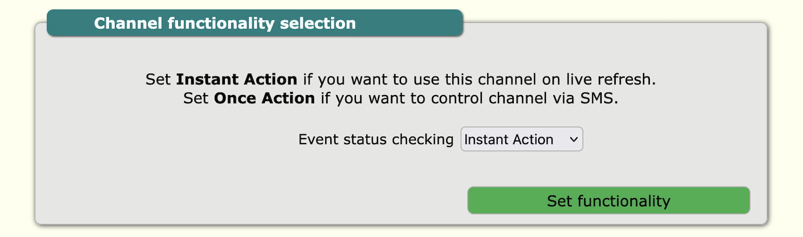
Channel functionality configuration
There are 2 options of channel functionality:
- Instant action
- Once action
If there is selected instant action the system is checking the schedule time table for this output every few second and correct the output status accordingly. We choose this configuration when we want to control the Gateway from internal schedule. In this mode of configuration the SMS and server commands on/off command are not working.
Once action allow to control by SMS, but in case of power failure the device will not return to previous status of outputs.
Manual ABC outputs control by website
There is individual tab for each output channel A, B, C. User can change status of output using internal website. This facility is for testing of outputs.

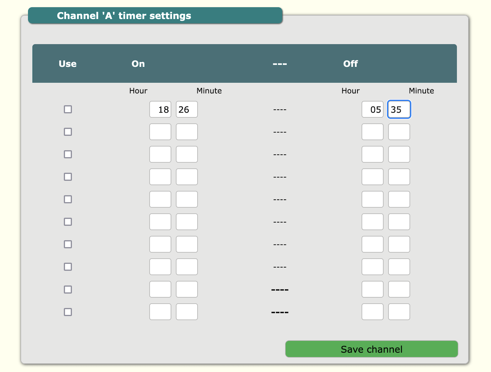
Schedule timers for control outputs
To control 3 outputs, device has 3 separate timetable with on/off schedule. Total timer schedule can implement up to 10 on/off sequence in 24h for each output.
In order to set the time of switching ON/OFF the Gateway A, B C outputs, all parameters for each output must be set separately. User also needs to select whether to use a given configuration. Maximum 10 schedulers can be added for every output.
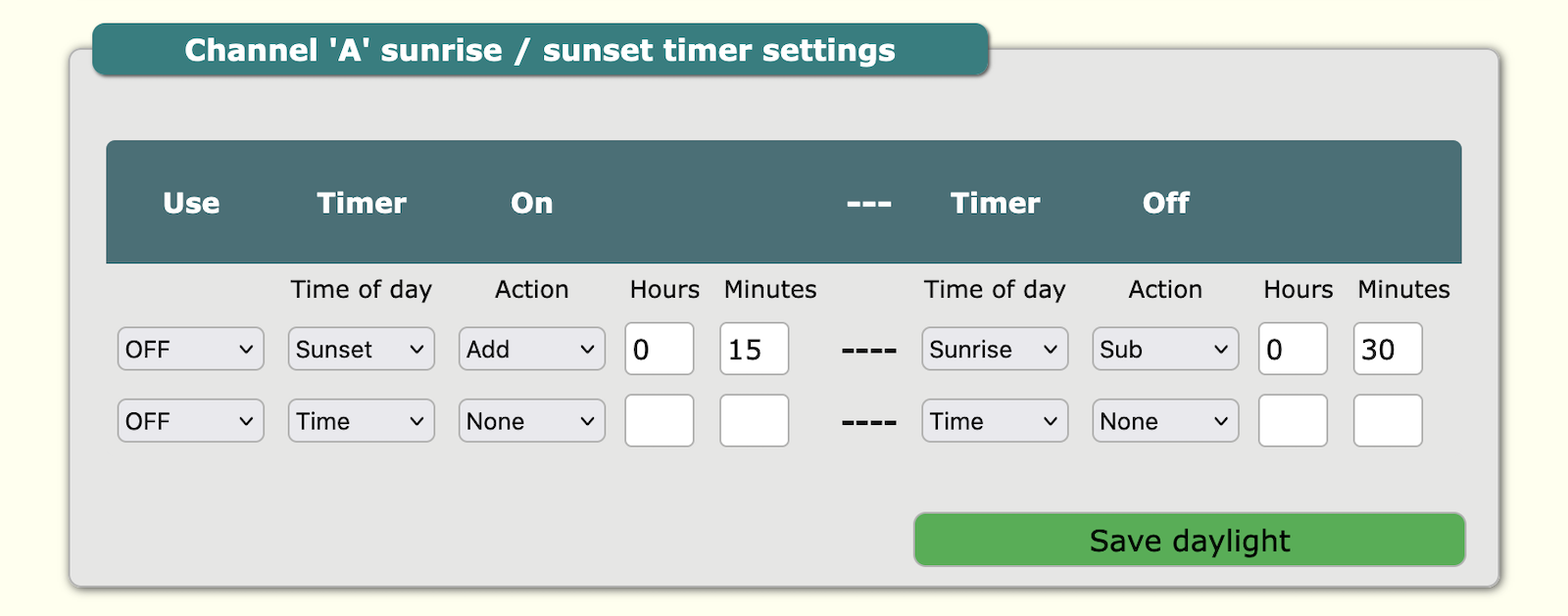
Astronomical timer
Device has 2 table position to switch on/off the outputs according to sunrise or sunset. The actual sunrise/sunset time is calculated from actual latitude and longitude and actual time. Latitude and longitude has to be entered manually in configuration web page or can be setted remotely.
The astronomical schedule is 2 ON and 2 OFF option for each output.
Output direct control by SMS
If you like to control Gateway's outputs direct by SMS only you have to set "once action". This configuration has to be apply for ABC outputs separately. For working with server user needs to set "INSTANT". More infoprmation in the SMS section.
Users - passwords
Password configuration
This section is for internal website access. Default password is atreyo.

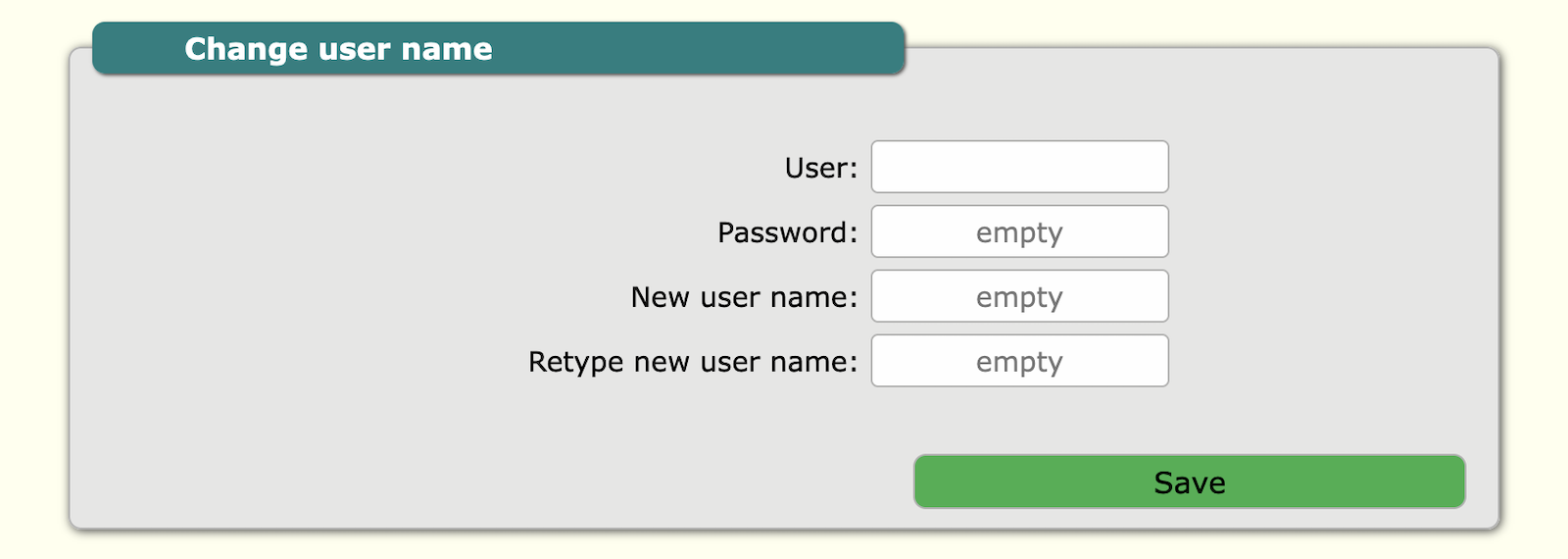
User configuration
For user change. Default user is atreyo.
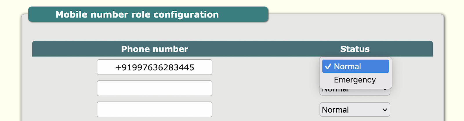
Permissions and role
This tab is for permissions of mobile numbers to protect from unauthorised access via SMS commands. By default any number can access Gateway but after input of any number only number from list is able to control Gateway. Mobile number has roles of "normal" and "emergency". Normal role allow to make control of Gateway, and emergency in addition is the emergency number for alerts. In AG-831 digital inputs high status is event for emergency SMS. It is possible to add maximum 13 telephone numbers. Number format with + before country prefix.
System
Multi-function reset button
The AG-811 has multifunction reset button. This button is used to:
- reset device
- restart device
- make default configuration
Multi-function reset button
The AG-811 has multifunction reset button. This button is used to:
- reset device
- restart device
- make default configuration
| Press and hold the reset button | Behaviour | Remark |
|---|---|---|
| 1 to 10 seconds | power off | If device is using battery backup |
| 10 to 20 seconds | restart device | |
| 20 to 30 seconds | make default | |
| 30 and more than 30 | exit |
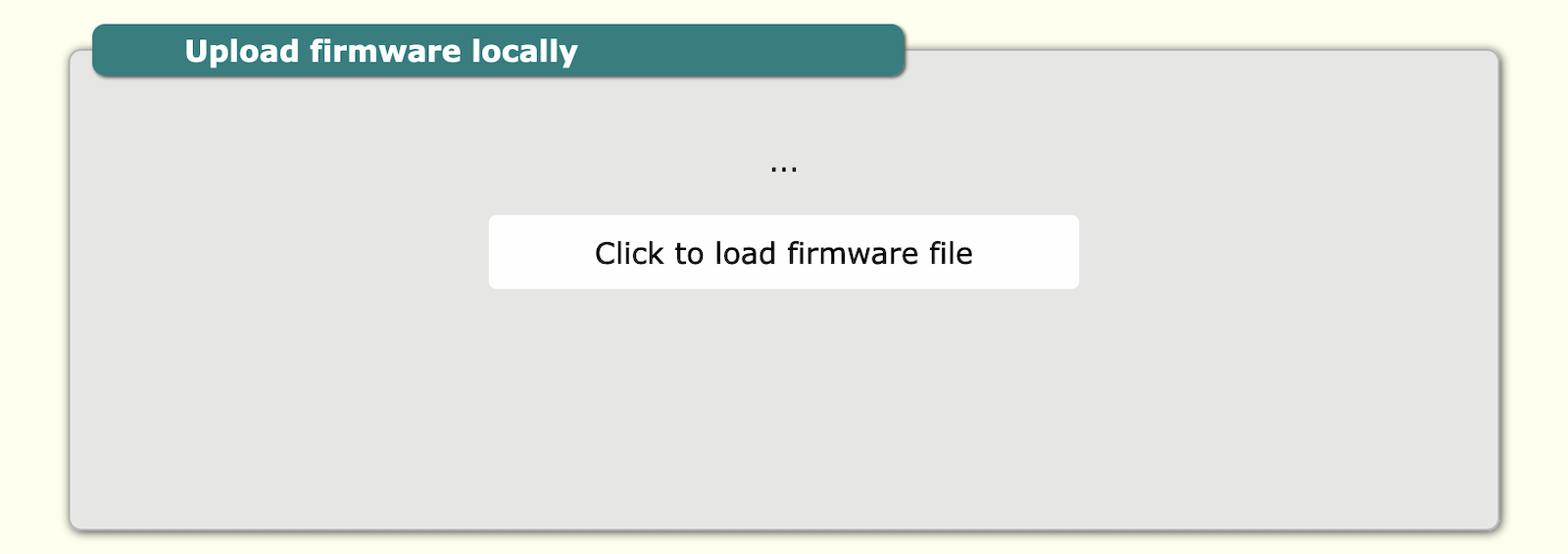
Firmware update
The Gateway can update firmware from remote URL and locally direct by uploading BIN file with proper firmware. To load firmware click load firmware file and select firmware. After loading Gateway will automaticity restart. Firmware update in normal condition will not reset configuration.
Local update
Update from server

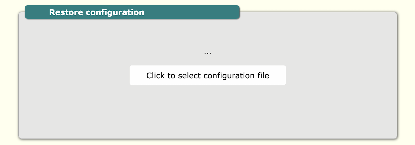
Backup / restore config
The gateway allows you to backup your configuration and also upload the configuration to the gateway. To do this, you need to enter the config section.
Local backup/restore

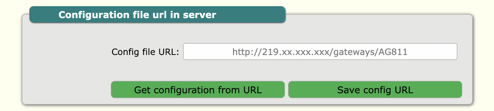
Configuration from server
Also, it is possible to download the configuration from the server. To do this, enter the correct address of the server and the configuration file.