General Information
| Download technical specification | Technical Specification |
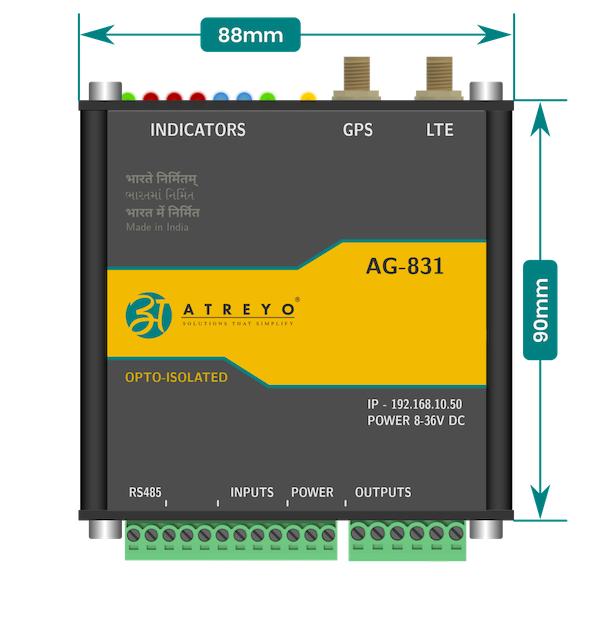
The AG-831 is a Gateway dedicated to work witch central controlling and monitoring systems. It support two-way communication with server trough LTE/GSM or Ethernet. It has inbuilt timer with 10 ON/OFF schedule within 24h, auto configurable sunrise/sunset timer based on geolocation and has 3 independent relays. Every output can be controlled by separate time schedule. Gateway has isolated Modbus RTU interface to communicate with energy meters, PLCs and other Modbus devices. Can be configured by: internal website, SMS, string from server and configuration file loaded in predefine URL. For accurate time and location it has GPS and RTC. This is updated version of AG-811.
- LTE and GSM connectivity
- GNSS for accurate time and location
- 3 independent NO outputs
- Opto-isolated Modbus RTU
- 2 opto-isolated digital inputs
- SMS alert and with mobile number filtering
- Timer with astronomical timer
- Internal website for configuration
- LAN with PoE
- Output status control by string from server and by SMS
- Modbus archive data in internal memory
- Aluminium compact size casing
- 35mm DIN rail mounting
Hardware informations
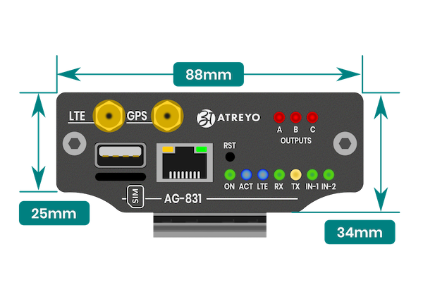
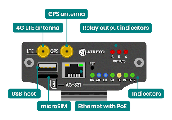
Top view
Side view
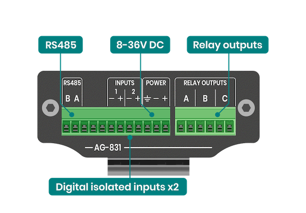
Connectors
The AG-831 has an RJ45 on the top with LED indicators and two SMA female sockets. There is also a two pluggable sockets on the bottom of the gateway.
Power supply
The device is powered by external DC power supply. Minimum supply voltage is 8V and maximum 36V. Preferred 24V. Select the power supply requirement according to the below table. The device had protection against high voltage and reverse polarity. High voltage will blow inbuilt fuse. Reverse voltage will not damage device – the device will simply not work on reverse voltage.
| Supply Voltage | Minimum A requirement | Suggested power supply rating |
| 12V | 1A |
1.5A |
| 15V |
1A |
1.5A |
| 24V |
0.5A |
0.7A |
| 32V |
0.5A |
0.5A |
PoE
The Gateway can also be powered via PoE in the range of 8-36V using unused pairs of wires in the LAN cable. Below is the pinout of the RJ45 socket.
| Pin number |
Function |
Comment |
| 1 |
RX+ | Data |
| 2 |
RX- | Data |
| 3 |
TX+ | Data |
| 4 |
DC+ | Power supply positive |
| 5 |
DC+ | Power supply positive |
| 6 |
TX- | Data |
| 7 |
DC- | Power supply negative |
| 8 |
DC- | Power supply negative |
LED indicators
The device has 10 LED indicators on the antenna side. On antenna side are power (green) and activity (yellow) indicator. The behaviour of activity LED is according to the table.
| LED | Function | Behaviour |
|---|---|---|
| POWER | Normal working condition | permanent ON |
| ACT | Normal working condition | blinking every 1 second |
| LTE | LTE/GSM connection | blinking if LTE/GSM active |
| Serial | RX and TX data indication of RS485 | blinking on data transfer |
| Inputs | Input 1 and 2 high level indication | ON if input high |
| Outputs | Out 1-3 ON | ON on output ON |