Understanding Device Details & Status
The Device Detail Page is your comprehensive monitoring dashboard for individual devices. It provides asystem complete,information, in-depthresource viewutilization, ofnetwork yourconnectivity device's operational status, technical specifications,details, and networkGPS health.location.

Accessing Device Detail Page
From Device List:
Navigate to Devices section
Locate target device in table
Click the device Name (underlined link)
Device Detail Page opens
Page Layout Overview
The Device Detail Page uses a two-column layout:
Left Panel: Static device identity and metadata
Right Panel: Dynamic monitoring data across four tabs
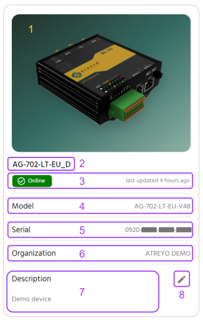
At-a-Glance Information (Left Side)Panel)
The left panel ondisplays the left provides the foundationalcore identity ofand information for your device:device.

# |
Field |
Description |
Example
1
Model Image
Visual representation of your device model.model
Gateway illustration
2
Device Name
Custom name you assigned during registration.registration
Delhi_Bus_207
3
Online Status
Connection thestate devicewith istimestamp
"Online since x5 timeminutes ago.ago"
4
Model Name
The specific product name of your hardware.gateway.
AG-207-LT-EU
5
Serial-ID
Unique 16-character device identifier
1A2B-3C4D-5E6F-7G8H
6
Organization
Assigned unitorganization
ATREYO assignedLevel-1
7
Description
Optional notes you addednotes/details about thedevice
"Factory Floor A, Bay 3"
8
Edit buttonButton
Pencil icon to modify description
Detailed View & Monitoring (Right Side)
On the right side, you'll find a Refresh Button and four dedicated tabs for technical monitoring:
Tab 1: Device Information
This tab provides the static, core technical specifications of your device's operating system and internal components.
System✏️ Information
Here are the definitions and examples for the requested System Information parameters:
Modem
Editing Device Description

To Edit Description:
Click Edit button (✏️ pencil icon)
Edit Description dialog opens
Modify text (max 1000 characters)
Click SAVE to confirm changes
Click CLOSE to discard changes
Use Cases for Description Field:
Physical location updates
Maintenance schedules
Contact information for site
Network configuration notes
Detailed Monitoring Tabs (Right Panel)
The right panel contains four tabs for in-depth device monitoring. A Refresh button (🔄) in the top-right corner manually updates tab data.

Device Information
Resource Utilization
Network Information
GPS Location
Tab 1: Device Information
This tab displays static technical specifications of your device's operating system, hardware, and cellular modem.
Section A: System Information
Core operating system and processor details.

|
Parameter |
Definition |
Example |
OS Name |
Operating |
OpenWRT, |
OS Platform |
OS |
Linux |
OS Version |
Specific |
10.0.22621, |
Architecture |
CPU |
ARMv7l, |
Host Name
Device model name
AG-702
Processor Name
CPU model designation
MIPS 24KEc V5.5, ARMv7 Processor rev 5
Section B: Modem Information
Cellular modem hardware and firmware specifications.

Parameter
Definition
Example
Model
Manufacturer's modem product designation
-
Firmware Version
Embedded software version number
V1.01.03, 2.1.25
IMEI
International Mobile Equipment Identity (15 digits)
123456789111111
Manufacturer
Company that produced the modem
-
Tab 2: Resource Utilization
This sectiontab is your device'sdevice Healthhealth Dashboard,dashboard, showing real-timeperformance performancemetrics and 24-hour historical usage.trends.

Metrics Cards
Three cards display current resource usage across critical components.

CPU Utilization
Displays:
-
Real-Time Data:View the count and utilization percentageNumber of CPU cores, totalRAM size and current usage, andtotal/used storage space. -
PerformanceCurrentGraphs:utilizationSee historical usage trends forCPU, RAM, and Storageover the last 24 hours (data is averaged every 1 minute).percentage
Example:
💡CPU:Health1Insight:Monitoring these resources helps ensure your device is running optimally and not experiencing bottlenecks.cores
Utilization: 45%
RAM Utilization
Displays:
Total RAM capacity
Currently used RAM
Utilization percentage
Example:
RAM: 128 MB total
Used: 66 MB (51.5%)
💡 Memory Management: High RAM usage isn't always problematic. Modern systems use available RAM efficiently. Concern arises when usage stays at 90%+ for extended periods.
Storage Utilization
Displays:
Total storage capacity
Used storage space
Utilization percentage
Example:
Storage: 512 MB total
Used: 270 MB (52.73%)
Common Storage Consumers:
Logs
Application data
24-Hour Performance Graphs
Below the real-time cards, three line graphs display historical resource usage trends.

Graph Specifications:
Time Range: Last 24 hours
Data Points: Every 1 minute
X-Axis: Time (hours)
Y-Axis: Utilization percentage (0-100%)
Graph Types:
CPU Usage Graph (Green line)
RAM Usage Graph (Blue line)
Storage Usage Graph (Yellow line)
Analyzing Performance Trends
Normal Patterns:
CPU:
Fluctuates based on workload
Spikes during data transmission or processing
Should return to baseline after tasks complete
RAM:
Typically steady with gradual increases
May step up when new processes start
Rarely decreases significantly without restart
Storage:
Gradually increases over time
Sudden jumps indicate large file writes
Decreases indicate log rotation or cleanup
Tab 3: Network Information
TrackThis thetab connectionprovides statusdetailed andconnectivity data usageinformation for both wired (Ethernet) and cellularwireless (Cellular) network interfaces.

The tab is organized into two sections:
Ethernet Card Information
Cellular Card Information
Section A: Ethernet Card Information
Wired network interface details for WAN (internet) and LAN (local network) connections.

Typical Display: Multiple ethernet interfaces may be shown (e.g., WAN, LAN, LAN2)
Ethernet Parameters
Parameter |
Definition |
Example
Interface Name
Logical network function identifier
WAN (e.g.internet-facing), WAN/LAN), Interface DeviceLAN (e.g.,local eth0.1,network)
br-lanInterface Device
OS-assigned hardware identifier
eth0.1 (VLAN sub-interface), APNbr-lan (bridge)
IPv4 Address
Network address for IPv4 communication
192.168.1.1 (router), unique IDs192.168.1.105 (client)
MAC Address
Unique 12-digit hardware identifier
00:1A:2B:3C:4D:5E
Download Speed
Current incoming data transfer rate
100 Mbps, 1 Gbps
Upload Speed
Current outgoing data transfer rate
50 Mbps, 900 Mbps
Downloaded Data
Total data received since last reset
5.2 GB, 1.3 TB
Uploaded Data
Total data transmitted since last reset
850 MB, 450 GB
IMSI,
Section B: Cellular Card Information
Wireless cellular network connectivity details for mobile or backup internet connections.

Cellular Parameters
Parameter
Definition
Example
Operator
Telecommunications carrier providing service
Vodafone, AT&T, T-Mobile, Airtel
APN
Access Point Name - Gateway for mobile internet
internet.voda.ie, broadband, airtelgprs.com
IMSI
International Mobile Subscriber Identity (15 digits)
310410123456789
IPv4
Mobile network IP address (version 4)
10.123.45.67 (carrier private IP)
IPv6
Mobile network IP address (version 6)
2001:0db8:85a3::8a2e:0370:7334
MSISDN),
SIM card number
+447700900000, 5551234567
ICCID
Integrated Circuit Card ID - SIM serial number
89014103210123456789
Signal Strength
Cellular signal quality in dBm
-75 dBm (excellent), and-110 dBm (poor)
Downloaded Data
Total Downloaded/cellular data received
2.1 GB
Uploaded Data.
Total cellular data transmitted
450 MB
Ethernet
Interpreting Information:Signal Strength
Signal strength is measured in dBm (decibel-milliwatts), a logarithmic scale where higher (less negative) values indicate stronger signals.
HereSignal areQuality the definitions and examples for the Ethernet card parameters:Scale:
dBm Range |
Quality |
Description |
Connectivity
-50 to -70
Excellent
Strong, clear signal
Full-speed data, reliable
-70 to -85
Good
eth0.1eth0br-lanAdequate signal
Good data speeds, stable
-85 to -100
Fair
Weak asignal
Reduced aspeeds, computer)occasional drops
-100 to -110
Poor
Very 00-1A-2B-3C-4D-5Eweak signal
Slow speeds, frequent disconnects
-110 to -120
Critical
Barely (Megabitsdetectable
Unusable, rateconstant atdrops
Factors Affecting Signal:
Distance from cell tower
Physical obstructions (buildings, terrain)
Weather conditions
Network congestion
Antenna quality and positioning
Cellular Troubleshooting Quick Guide
Problem: Poor Signal Strength (<-100 dBm)
Solutions:
Antenna Positioning: Relocate device or adjust external antenna
Alternative Location: Move device to higher elevation or near window
Problem: No Cellular Card Information:Connection
HereCheck:
✅ SIM card inserted correctly
✅ Carrier account is active and examplespaid
✅ APN settings match carrier requirements
✅ Device is in carrier coverage area
✅ IMEI is not blocked by carrier
Problem: High Data Usage
Investigate:
Check Downloaded/Uploaded Data totals
Review application data transmission settings
Confirm data is being sent via cellular (not ethernet)
Look for unauthorized usage or malware
Tab 4: GPS Location
This tab manages device location tracking through automatic GPS data or manual coordinate entry.

Location Tracking Modes
The tab offers two mutually exclusive modes:
Auto Mode: Automatic GPS tracking
Manual Mode: User-defined coordinates
Option A: Auto Mode
Automatic location tracking using the device's internal GPS modem.

How It Works:
Device's cellular cardmodem information:contains GPS receiver
Modem locks onto GPS satellites (requires 4+ satellites)
Location data calculated on device
Coordinates transmitted to Atra RMS
Map updates automatically
GPS Data Fields
When Auto mode is active and GPS has a fix, the following data is displayed:

Field |
Description |
Example |
Coordinates |
Latitude |
23.0225° |
Altitude |
Height |
45 meters (147.6 feet) |
Speed |
Current |
60 km/h ( |
Direction/Course |
Compass |
270° (West), 45° (Northeast) |
Fix |
Position |
"3D Fix" (lat, lon, alt) |
Satellites |
Number |
8 satellites |
HDOP |
Horizontal |
1.2 ( |
Validity |
Data |
'A' ( |
invalid)
Tab 4: GPS Location
This tab manages how the device's physical location is tracked. You have two options: Auto or Manual.
Option: Auto (Recommended for Mobile Devices)
The device automatically sends location data obtained from its modem to the cloud. This is ideal for devices mounted on vehicles or where real-time location tracking is essential.
GPS Time
Timestamp offrom theGPS devicesatellite abovesystem
2025-12-31 of14:30:45 changeUTC
Option:Understanding ManualGPS Accuracy
IfSatellites theCount:
4+ satellites: Minimum for 3D fix (lat, lon, altitude)
3 satellites: 2D fix only (lat, lon, no altitude)
8-12 satellites: Optimal accuracy
<3 satellites: No position fix possible
HDOP (Horizontal Dilution of Precision):
Quality Indicator: Lower values = better accuracy
Scale:
1.0-2.0: Excellent (typical accuracy: 1-3 meters)
2.0-5.0: Good (typical accuracy: 3-10 meters)
5.0-10.0: Moderate (typical accuracy: 10-30 meters)
>10.0: Poor (accuracy degraded)
Validity Codes:
'A' (Active/Valid): GPS data is current and reliable
'V' (Void/Invalid): GPS data is stale or unreliable
GPS Troubleshooting
Problem: No GPS Fix
Common Causes:
❌ Device is indoors (GPS requires clear sky view)
❌ Device is in metal enclosure (blocks signals)
❌ GPS antenna not connected properly
❌ Location service disabled in device settings
Solutions:
Move Device: Place near window or outdoors temporarily
Check Antenna: Verify external GPS antenna connection
Wait: First fix can take 5-15 minutes ("cold start")
Verify Settings: Ensure GPS service is disabledenabled
Problem: Poor Accuracy (High HDOP)
Solutions:
Improve Sky View: Remove obstructions above device
Wait: Accuracy improves as more satellites are acquired
External Antenna: Use high-quality external GPS antenna
Check Environment: Avoid placement near RF interference sources
Use Cases for Auto GPS Mode
Ideal Scenarios:
✅ Vehicle-mounted devices (fleet tracking)
✅ Mobile equipment monitoring
✅ Temporary installations requiring location verification
✅ Asset tracking applications
✅ Devices requiring location-based automation
Not Recommended:
❌ Stationary indoor installations
❌ Underground or unavailable,heavily youshielded canlocations
❌ device'sLocations with poor GPS visibility
Option B: Manual Mode
User-defined static location (coordinates.

How It Works:
User enters Latitude and Longitude).Longitude manually
Coordinates stored in cloud only
Location displayed on Overview map
No data transmitted from device
Manual Location Entry

Input Fields:
Latitude:
Format: Decimal degrees
Range: -90° to +90°
North: Positive values
South: Negative values
Example: 23.0225 (23° N)
Longitude:
Format: Decimal degrees
Range: -180° to +180°
East: Positive values
West: Negative values
Example: 72.5714 (72° E)
Finding Coordinates for Manual Entry
Method 1: Google Maps
Open Google Maps (maps.google.com)
Right-click on desired location
Click "What's here?"
Coordinates appear at bottom (click to copy)
Format: Latitude, Longitude (e.g., 23.0225, 72.5714)
Method 2: GPS Device/Phone
Use smartphone GPS app
Stand at device location
Record coordinates from app
Enter into Manual Location fields
Method 3: Physical Address Lookup
Use geocoding service (e.g., geocode.xyz)
Enter physical address
Service returns coordinates
Verify accuracy on map before using
Important Limitations of Manual Mode
⚠️ ImportantCritical Note:Understanding:
Manual location data is stored onlyONLY in the cloudcloud, and notNOT on the device. The physical location of the device may differ from the location you set manually.
device.
Implications:
💭FAQs
How do I get to the Device Detail Page?
From the Device List Page, simply click on the name of the device you wish to inspect. This will take you directly to its detail page.
What is the most important information on the Device Detail Page for troubleshooting?
Look at the Resource Utilization tab. This section shows real-time usage for CPU, RAM, and Storage, along with 24-hour historical graphs. This data gives you immediate insight into the device's health and performance.
What does a low HDOP value mean in the GPS Location tab?
HDOP stands for Horizontal Dilution of Precision. A low HDOP value (typically between 1 and 2) is a good thing! It means the satellite signals are well-distributed, giving you a more accurate device position.
What's the difference between "Auto" and "Manual" GPS location?
-
Auto:MapTheDisplay:deviceDeviceautomaticallyappearssendsatreal-timemanual locationdataongatheredOverviewfrom its internal modem.map -
Manual:DeviceYouReality:manuallyPhysicalenterdevicethehascoordinates.noThisknowledgedataofisthisstoredlocationonly
Mismatch cloud,Possible: notDevice onmay thebe device,physically and is used when the device's physical GPS service is unavailable.elsewhere
⚠️ Use Manual Mode Only When:
GPS is unavailable (indoor, underground, shielded locations)
Device is stationary and location won't change
Approximate location is sufficient for your needs
You understand the location is for reference only
Use Cases for Manual Mode
Appropriate Scenarios:
✅ Fixed indoor installations (factories, server rooms)
✅ Underground installations (basements, tunnels)
✅ Devices in GPS-shielded enclosures
✅ Legacy devices without GPS capability
✅ Approximate location sufficient for inventory purposes
Not Recommended:
❌ Mobile devices requiring real-time tracking
❌ Situations requiring precise location verification
❌ Applications with location-based automation
❌ Compliance scenarios requiring actual device location